


How to Set Feed Rate for Indexable Drills: The Definitive Guide
Mastering your feed rate setup is the single most critical factor in maximizing the lifespan of indexable drills. If you run too slow, you rub the inserts and work-harden the material; run too fast, and you risk catastrophic insert failure. This guide cuts through the noise to give you the practical, shop-floor reality of dialing in your CNC parameters for peak performance.
What Is the Ideal Feed Rate Setup for Indexable Drills?
The ideal feed rate setup for indexable drills relies on balancing Surface Feet Per Minute (SFM) and chip load based on material hardness. Generally, you should aim for a feed rate between 0.003″ and 0.012″ per revolution (IPR), depending on the drill diameter and insert geometry. Always start at the manufacturer’s median recommendation and adjust based on chip formation and spindle load.
The Mechanics of the Setup
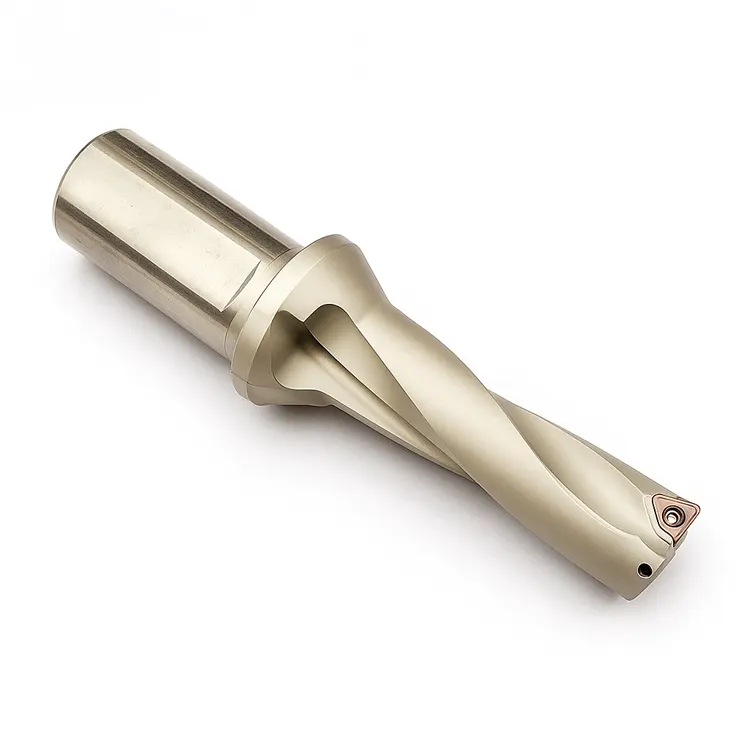
Getting the feed rate setup right isn’t just about punching numbers into the controller. It is about understanding the physics occurring at the cutting edge. Unlike solid carbide drills, indexable drills (often called U-drills or inserted drills) use two distinct inserts: a central insert and a peripheral insert.
These two inserts perform different jobs. The central insert cuts at effectively zero surface speed (at the very center), while the peripheral insert creates the bore size. Your feed rate must be aggressive enough to break the chip on the inner insert. If you baby the feed rate, the inner insert will merely rub, creating heat rather than chips, leading to premature failure.
Machinist’s Note: I’ve seen countless operators reduce the feed rate when they hear a “thump” at the entry. With indexable drills, that is usually a mistake. These drills need pressure to stabilize. Reducing feed often increases chatter.
How Do You Calculate RPM and Feed Rate Correctly?
To calculate the correct parameters, you must first determine the RPM using the formula $(SFM \times 3.82) / Drill Diameter$, and then calculate the Feed Rate (IPM) using $RPM \times Chip Load per Revolution$. Accurate calculation prevents work-hardening and ensures the inserts shear the metal rather than plowing through it.
Breaking Down the Math
You cannot guess these numbers. Here is the step-by-step workflow to nail your feed rate setup every time.
1. Determine Surface Feet Per Minute (SFM)
Consult your insert box. It will give you a range (e.g., 400-800 SFM for 4140 Steel).
- Roughing: Aim for the lower end of the SFM range.
- Finishing/High Production: Aim for the higher end.
2. Calculate RPM
$$RPM = \frac{SFM \times 3.82}{Drill Diameter}$$
Example:
- Material: 1018 Steel (Target 600 SFM)
- Drill: 1.00″ Indexable
- $RPM = (600 \times 3.82) / 1 = 2292 RPM$
3. Determine Feed Rate
Indexable drills are rated in Inches Per Revolution (IPR). A standard 1-inch drill in steel typically wants 0.005″ to 0.008″ IPR.
- Formula: $Feed (IPM) = RPM \times IPR$
- Calculation: $2292 \times 0.006 = 13.75 IPM$
If you are struggling to dial in your initial parameters across different tools, reviewing a holistic CNC setup optimization guide can help you standardize these calculations across the shop.
Why Does Material Hardness Change Your Feed Rate Strategy?
Material hardness dictates the chip load the insert can withstand; harder materials (like Inconel or H13 tool steel) require lower surface speeds and lighter feed rates to prevent thermal cracking, while softer materials (like Aluminum or 1018) demand higher speeds and aggressive feeds to ensure proper chip evacuation.
Material-Specific Feed Guidelines
When planning your feed rate setup, the material is the boss. Here is a quick reference table for starting points on a standard 1-inch indexable drill:
| Material Group | ISO Code | Starting SFM | Starting Feed (IPR) | Strategy |
| Low Carbon Steel | P | 600 – 900 | 0.006 – 0.010 | Push hard to break chips. |
| Alloy Steel (4140) | P | 350 – 600 | 0.004 – 0.008 | Monitor spindle load closely. |
| Stainless Steel (304/316) | M | 300 – 500 | 0.003 – 0.006 | Keep entry constant to avoid work hardening. |
| Cast Iron | K | 400 – 700 | 0.008 – 0.012 | Abrasive; watch for flank wear. |
| Aluminum | N | 1000+ | 0.010 – 0.015 | Maximum evacuation required. |
The “Gummy” Material Danger
In materials like Stainless Steel or low-carbon steel, a low feed rate is dangerous. Long, stringy chips will wrap around the drill body (bird-nesting). You must increase the feed rate to force the chip to snap against the drill flute.
How Do You Troubleshoot Chatter During Drilling?
Chatter is usually caused by a lack of rigidity or insufficient feed pressure; to fix it, increase your feed rate by 10-20% to stabilize the cut, ensure the workpiece is clamped securely, and check that the tool overhang is kept to an absolute minimum (ideally less than 3x diameter).
Solving the Vibration Issue
It sounds counter-intuitive to newer machinists, but speed kills stability, while feed creates it.
When a drill chatters (screams), it is bouncing.
- Increase Feed: Pushing the tool harder forces it into the cut, dampening the vibration.
- Check Runout: Indexable drills are sensitive. Total Indicated Runout (TIR) should be under 0.002″.
- Analyze the Chips:
- Powder/Dust: Feed is too light.
- Long Stringers: Feed is too light or speed is too low.
- Tight “6” or “9” shapes: Perfect setup.
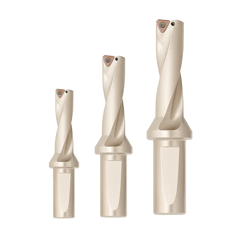
When Should You Adjust Feed Rate for Deep Holes?
For holes deeper than 3x diameter (3xD), you generally do not need to peck, but you must ensure coolant pressure is high; however, for 4xD or 5xD drills, you may need to reduce the feed rate by 10-20% at the entry and exit to minimize deflection and ensure hole straightness.
The Myth of Peck Drilling
Do not peck drill with indexable drills unless absolutely necessary. Pecking causes the inserts to re-enter the cut repeatedly, which is the number one cause of chipped edges on carbide inserts.
Instead of pecking, optimize your feed rate setup for continuous cutting:
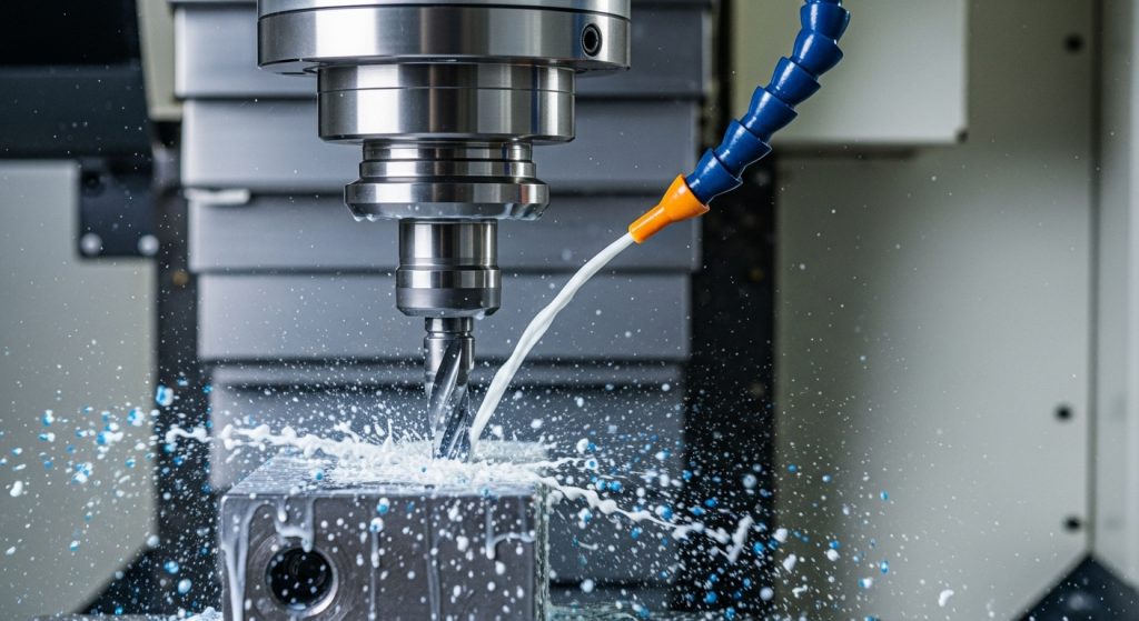
- High Coolant Pressure: Through-spindle coolant (TSC) is non-negotiable for deep indexable drilling. It blasts chips out of the hole.
- Entry/Exit Feeds: If you are drilling through a rough surface or exiting an uneven surface, reduce feed to 50% for the first and last 0.100″ of the cut. This protects the peripheral insert from snapping as it breaks out.
How Do You Read Chips to Verify Feed Rate?
Reading chips involves inspecting their shape and color: blue or purple chips indicate heat is being removed correctly in steel, while silver chips suggest insufficient heat generation; tight, C-shaped chips confirm the feed rate is optimal, whereas long, unmanageable ribbons indicate the feed rate is too low.
The Chip Tells the Truth
Your machine display might say 100% load, but the chips tell the real story of your feed rate setup.
- The “C” and “9” Shape: This is the holy grail. It means the chip breaker on the insert is engaging.
- The Bird’s Nest: If you open the door and find a ball of wire wrapped around the tool, you are running too light. Increase feed immediately.
- Discolored Inserts: If the chips are silver but the inserts are black/burnt, you are generating heat but not evacuating it. This is usually a coolant volume issue or a dwell issue.
Pro Tip: Never dwell at the bottom of a hole with an indexable drill. The moment you reach Z-depth, retract immediately. Dwelling rubs the inserts against the bottom, destroying the edge instantly.
Conclusion: Confidence in Your Cut
Dialing in the perfect feed rate setup for indexable drills is a blend of math and observation. Start with the formulas, trust the manufacturer’s baseline, but always listen to the machine. If it screams, push it harder. If it crunches, back off.
Remember, an indexable drill is a high-performance roughing tool. It wants to work. Don’t be afraid to give it the feed it demands.