


How to Diagnose Poor Hole Surface Finish
Is rough hole finish causing scrapped parts? Learn to distinguish between chatter, feed marks, and smearing. Expert diagnostic guide from Accurate Cut.
A hole is rarely just empty space; in precision manufacturing, it is a functional feature. Whether it acts as a hydraulic port, a bearing seat, or a clearance hole for a fastener, the surface finish defines its performance. Poor finish leads to seal failures, fatigue cracks, and assembly rejection.
Indexable drills are designed primarily as high-efficiency “hole openers.” While they are not boring bars, modern indexable technology should deliver a consistent, acceptable finish (typically Ra 63-125 micro-inches). When the surface finish degrades beyond this standard, it is not just a cosmetic issue—it is a “fingerprint” of mechanical or thermal instability.
At Accurate Cut, we categorize surface finish failures into specific “symptoms.” By reading the marks left on the hole wall, you can diagnose the root cause—be it vibration, chip packing, or built-up edge—and apply the correct engineering fix.
The Language of Surface Finish (Ra vs. Rz)
Before diagnosing the problem, we must define the standard. In the US manufacturing sector, we primarily use Ra (Average Roughness).
- Ra: The arithmetic average of the roughness profile. It gives a general idea of surface texture.
- Rz: The mean roughness depth (the distance between the highest peak and lowest valley).
Setting Expectations
Indexable drills are balanced to remove material quickly.
- Standard Indexable Finish: Ra 63 to 125.
- High-Performance/Wiper Finish: Ra 32 to 63.
If you are requiring a finish better than Ra 32, a drill is likely the wrong tool for the final pass. However, if your drill should be producing an Ra 63 but is producing an Ra 250, you have a diagnostic problem to solve.
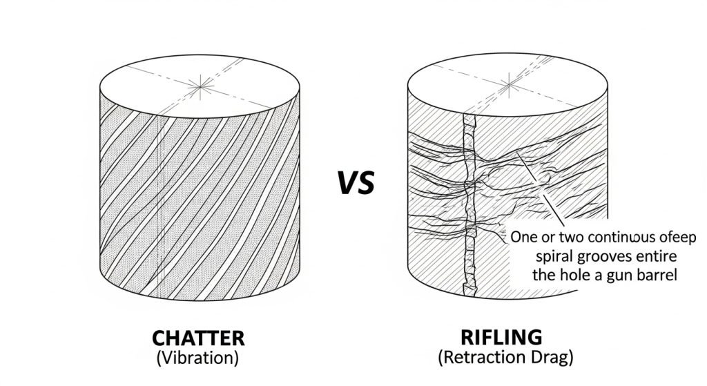
Chatter Marks (Vibration)
The Visual:
The surface has a distinct, repetitive pattern. It often looks like “tiger stripes,” a checkerboard pattern, or localized gouges that repeat at specific intervals.
The Root Cause:
This is Regenerative Chatter. The drill is vibrating (bouncing) against the workpiece. This is a stability issue, often caused by the tool reacting to the frequency of the machine or the part.
The Fix:
Many operators instinctively slow down the RPM when they hear chatter. While this changes the frequency, it often doesn’t solve the root instability.
- Check Overhang: Is the drill extending more than 3x its diameter (3xD) without support? Rigidity decreases exponentially with length.
- Increase Feed: Paradoxically, increasing the feed rate can eliminate chatter. Heavier feed pressure stabilizes the tool by keeping it engaged in the cut, preventing it from bouncing.
- Check Runout: If the tool is whipping, it will chatter. Review our guide on how to prevent chipping in drill inserts to see how runout destroys tool stability.
“Rifling” or Spiral Drag Lines
The Visual:
The hole looks like a gun barrel. There are one or two deep, continuous spiral grooves running the length of the hole.
The Root Cause:
This is almost always a Retraction Issue.
- Drag on Exit: The drill cuts the hole to size, but as it retracts (rapids out), the drill body or the insert drags along the wall.
- Bent Drill Body: If the drill body has been crashed previously, it may be slightly bent. It cuts an oversized hole on the way down (due to runout) and drags on the way up.
The Fix:
- Turret Alignment: On a lathe, check that the drill is perfectly concentric with the spindle.
- Body Inspection: A compromised drill body cannot produce a round hole. If you suspect body damage, refer to our industrial drill maintenance and buying guide.
Smearing and Torn Material
The Visual:
The surface looks cloudy, dull, or “plucked.” Instead of clean cut lines, the metal looks like it was torn away. This is very common in aluminum, stainless steel, and low-carbon steels.
The Root Cause:
This is caused by Built-Up Edge (BUE). Material is welding to the cutting edge due to heat or lack of lubricity. As the drill rotates, this welded material rubs against the wall (smearing) or breaks off, tearing the surface.
The Fix:
- Increase Coolant Concentration: You need lubricity, not just cooling. Ensure your mix is 10-12% Brix. Optimizing coolant is also a critical step in how to extend indexable drill tool life.
- Increase Speed (SFM): In materials like stainless, running too slow causes the material to stick. increasing speed generates enough heat to plasticize the chip flow, resulting in a cleaner shear.
- Check Coating: Ensure you are using a polished or smooth-coated insert to reduce friction.
Vertical Scoring (Scratches)
The Visual:
Straight, non-spiral lines running vertically down the length of the hole.
The Root Cause:
This is a Chip Evacuation Failure. The chips are not breaking or flushing out. Instead, they are getting trapped between the drill body and the hole wall, scoring the surface as they are forced out.
The Fix:
- Coolant Pressure: Volume helps, but pressure is required to force chips up the flutes.
- Chip Breaking: If you are producing long, stringy chips, they will score the wall. Increase your feed rate to break the chips into small “6s” and “9s.”
For a deeper analysis of how chip issues lead to tool failure, read our article on why drill inserts break.
The Wiper Insert Solution
If your diagnostic checks are clear—stability is good, chips are breaking, and coolant is rich—but you still need a better surface finish, consider Wiper Geometry.
Standard indexable inserts have a small corner radius. “Wiper” inserts feature a modified geometry on the peripheral cutting edge that acts like a small flat. This flat “wipes” or smoothes the feed lines left by the cutting action, significantly lowering the Ra value without changing cutting parameters.
Conclusion
Surface finish tells a story. It is the signature of the cutting forces, temperatures, and mechanics occurring inside the hole. By learning to distinguish between the vibration of chatter, the drag of retraction, and the cloudiness of BUE, you can stop guessing and start engineering a solution.
At Accurate Cut, we design our drills to balance metal removal rates with surface quality. If you are struggling to meet finish requirements, verify your setup against these symptoms, or contact our technical team for an application review.
Frequently Asked Questions
Why is the finish worse at the bottom of the hole?
This is usually due to chip packing or coolant starvation. As the drill gets deeper, it becomes harder to flush chips out. If chips accumulate at the bottom, they grind against the wall. Pecker drilling (pecking) is generally not recommended for indexable drills; instead, increase coolant pressure.
Can I use a dwell at the bottom to improve finish?
No. Never dwell with an indexable drill. If the tool rotates without feeding, it rubs against the bottom of the hole. This causes immediate work hardening (glazing) and chatter, which ruins the surface finish and dramatically shortens tool life.
Does runout affect surface finish?
Yes. If a drill has runout, the peripheral insert takes an uneven “bite” with every revolution. This creates a “rifling” pattern and makes the hole slightly oval-shaped. We recommend maintaining a Total Indicated Runout (TIR) of less than 0.002″.