


How to Identify Drill Insert Wear Patterns
The most expensive sound in a machine shop isn’t the whir of the spindle or the hum of the conveyor—it’s the sickening “crunch” of a drill failure inside a finished part.
In high-production manufacturing, indexable drilling is the backbone of hole-making efficiency. But unlike turning or milling, drilling happens in a semi-enclosed environment. You can’t always see the wear developing until it’s too late. When an insert fails catastrophically, it doesn’t just cost you an edge; it often destroys the expensive drill body and scraps the workpiece.
At Accurate Cut, we believe that tool life shouldn’t be a guessing game. While zero wear is impossible, predictable wear is the goal. By understanding the specific wear mechanics of indexable drills—which differ significantly from stationary turning tools—you can optimize your parameters, protect your tool bodies, and maintain process security.
Here is our comprehensive technical guide to reading your drill inserts and diagnosing the root causes of failure.
The Unique Dynamics of Indexable Drilling
Before analyzing specific wear patterns, it is critical to understand why indexable drills fail differently than other cutting tools.
In a turning operation, the cutting speed is relatively constant across the engagement area. In indexable drilling, you are dealing with two distinct cutting environments simultaneously on the same tool body. This creates a “velocity gap” that dictates how wear appears.
The Peripheral (Outer) Insert
This insert travels the furthest distance per revolution. It operates at the maximum cutting speed ($V_c$) and generates the most heat. Consequently, the peripheral insert is most prone to abrasive wear and thermal deformation.
The Central (Inner) Insert
This insert operates near the center of the hole where the surface speed drops effectively to zero. It doesn’t “cut” as much as it “extrudes” or pushes material out of the way. It faces immense mechanical pressure and crushing forces. Therefore, the central insert is most prone to chipping and fracture.
If you treat both inserts the same, you will never optimize your process. You often need a tougher grade on the inside (to resist shock) and a harder, wear-resistant grade on the outside (to resist heat).
Essential Wear Patterns: Identification & Solutions
When you pull a drill for inspection, don’t just look for “damage.” Look for the story the insert is telling you about the cutting conditions. Here are the most common failure modes we see in our lab and how to fix them.
Flank Wear (Abrasive Wear)
Identification:
You will see a relatively uniform abrasive flat spot on the relief face (the side of the insert rubbing against the newly cut hole). This is the most desirable form of wear because it is predictable.
The Limit:
For most general drilling applications, a wear land ($V_B$) of 0.3mm is the changing point. If you are holding tight tolerances (IT9 or better), you may need to index at 0.2mm.
Root Cause:
- Normal Operation: All tools wear. This is chemical and mechanical abrasion from the workpiece material.
- Rapid Progression: If flank wear develops too quickly, your cutting speed ($V_c$) is likely too high, or the carbide grade lacks abrasion resistance.
Corrective Action:
- Reduce cutting speed.
- Select a harder carbide grade or a thicker coating (such as CVD coating for steels).
- Check coolant concentration; poor lubricity increases friction.
Built-Up Edge (BUE)
Identification:
Material from the workpiece welds onto the cutting edge, altering the geometry. It looks like a shiny, jagged layer of metal sitting on top of the insert tip. When this built-up material eventually breaks away, it pulls chunks of the insert coating or substrate with it.
Root Cause:
BUE is a temperature issue—specifically, the temperature is too low. It is common in “sticky” materials like stainless steel, aluminum, and low-carbon steels.
- Cutting speed is too low (not enough heat to plasticize the chip).
- Cutting edge is too dull for the material.
Corrective Action:
- Increase Cutting Speed: This raises the temperature in the shear zone, allowing chips to flow rather than stick.
- Increase Coolant Pressure: Help evacuate the chips before they can re-weld.
- Sharp Geometry: Switch to a positive geometry insert with a sharp edge preparation. Refer to our drill insert coatings guide to find PVD coated grades which are usually sharper.
Chipping and Fracture
Identification:
- Chipping: Small notches or jagged jaggedness along the cutting edge.
- Fracture: Large pieces of the insert missing, often destroying the seat pocket.
Root Cause:
This is a mechanical stability issue. It is most frequently seen on the Central Insert due to the unstable cutting conditions at the center of the hole.
- Feed rate ($f_n$) is too high.
- Setup is unstable (vibration).
- Excessive runout on the spindle or tool holder.
- Interrupted cuts (cross-holes).
Corrective Action:
- Reduce feed per revolution ($f_n$) at the entrance and exit.
- Check Total Indicated Runout (TIR). For high-performance drilling, runout should be under 0.02mm.
- Use a “tougher” carbide grade (higher cobalt content) for the central insert.
Crater Wear
Identification:
A divot or depression forms on the rake face (the top surface) of the insert where the chip flows.
Root Cause:
Chemical wear caused by extreme heat and pressure. Elements from the workpiece material diffuse into the carbide substrate. This is common when drilling aggressive steels at high speeds on the Peripheral Insert.
Corrective Action:
- Reduce cutting speed to lower the temperature.
- Select a grade with a high aluminum oxide ($Al_2O_3$) content, which chemically resists cratering.
Plastic Deformation
Identification:
The cutting edge looks like it is slumping, bulging, or curling downward. Unlike chipping, the material is still there, but it has lost its shape.
Root Cause:
The cutting temperature has exceeded the thermal limits of the carbide binder. The substrate is literally softening.
Corrective Action:
- Drastically reduce cutting speed.
- Reduce feed rate to lower mechanical pressure.
- Switch to a grade with higher “hot hardness.”
Thermal Cracking (Comb Cracks)
Identification:
Small cracks running perpendicular to the cutting edge. They look like the teeth of a comb.
Root Cause:
Thermal shock. This happens when the insert heats up during the cut and is rapidly cooled by coolant, repeatedly. It is common in interrupted cuts or when coolant supply is inconsistent (trickling rather than flooding).
Corrective Action:
- Flood or Starve: Either maximize coolant pressure to keep the tool consistently cool, or (in rare cases with specific grades) run dry.
- Ensure coolant is directed straight at the cutting zone, not deflected by chips.
Troubleshooting by Sound and Chip Formation
You shouldn’t wait until the tool is removed to check for wear. Your machine is giving you sensory feedback constantly.
The “Screech”
A high-pitched squealing usually indicates excessive flank wear on the peripheral insert. The clearance angle has been worn away, and the side of the insert is rubbing against the hole wall.
The “Pop” or “Thump”
A low-frequency thumping sound often indicates that the chips are not evacuating. They are packing in the flutes. If you hear a loud “pop,” the central insert may have just fractured.
Reading the Chips
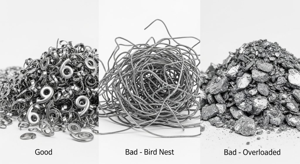
The shape of the chip is the best indicator of drilling health.
- Ideal: Tight “6” or “9” shaped spirals. This indicates proper chip breaking and evacuation.
- Danger: Long, stringy bird nests. These wrap around the tool body, blocking coolant and causing catastrophic heat buildup.
- Warning: Very tight, thick chips. This indicates excessive power consumption and potential for plastic deformation.
When to Change the Insert: The Economic Balance
One of the most common questions our technical team receives is: “Can I run this insert for 50 more holes?”
The answer lies in the balance between insert cost and tool body cost.
The 90% Rule
We recommend changing inserts when they reach approximately 80-90% of their theoretical life. Why? Because the last 10% of life is unpredictable. If an insert fails in the hole, it can weld to the steel drill body pocket.
A $15 insert is not worth risking a $400 drill body.
The “Both or Nothing” Protocol
Operators often try to save money by only rotating the worn insert (usually the peripheral one) while leaving the central insert alone.
Do not do this.
Indexable drills are engineered for balanced force. If you have a sharp peripheral insert and a dull central insert, the drill will wander, creating hole deviation and putting uneven stress on the tool body. Always index or change both inserts simultaneously.
Key Indicators for Changing
- Visual: Flank wear exceeds 0.3mm.
- Load Meter: Spindle load increases by 10-15% over the baseline of a fresh tool.
- Surface Finish: The hole finish becomes rough or shows “rifling” marks.
- Hole Size: The hole diameter begins to shrink (due to peripheral wear).
FAQ: Common Drilling Issues
Why is my central insert chipping but the outer one is fine?
This is typically a stability issue. The central insert takes the brunt of the mechanical force. Check your feed rate (it may be too high for the material), ensure your workpiece is clamped securely, and check the spindle for runout.
Can I run indexable drills dry?
Generally, no. Unlike milling, drilling evacuates chips through a confined space. Coolant is necessary not just for cooling, but for flushing chips out of the hole. Running dry usually leads to chip packing and seizure, unless you are drilling cast iron or using specific high-temp grades.
What causes rapid flank wear in stainless steel?
Stainless steel work-hardens rapidly. If your drill dwells or rubs, the surface hardens, and the insert abrades quickly. Ensure you maintain a constant, positive feed rate. Do not baby the tool in the cut.
How do I know if my coolant pressure is sufficient?
For indexable drills (especially 3xD and deeper), volume is more important than just pressure. You need enough flow to flush chips. If you see chips being re-cut (shiny, smaller pieces mixed with normal chips), your evacuation is poor.
Is built-up edge always bad?
Yes. While a small amount of stable BUE can sometimes protect the substrate, in drilling, it is too unstable. It changes the hole tolerance and eventually leads to edge chipping. Aim to eliminate it by increasing speed or coolant concentration.
Conclusion
Identifying drill insert wear patterns is about more than just saving money on carbide—it is about Process Security. By distinguishing between the needs of the inner and outer inserts, and monitoring the “vital signs” of your process (sound, load, and chip shape), you can transform your drilling operations from a bottleneck into a reliable, predictable asset.
Remember, the goal is not to run the tool until it breaks. The goal is to run the tool until it has done its job efficiently, and then change it before it costs you a body or a part.
If you are struggling with unpredictable tool life or need help selecting the right grades for your specific alloys, contact the engineering team at Accurate Cut. We are ready to help you dial in your parameters for maximum profitability.