


How to Prevent Chipping in Drill Inserts
Is insert chipping ruining your tool life? Learn to diagnose mechanical shock, runout, and grade selection errors. Expert prevention tips from Accurate Cut.
In high-production drilling, chipping is often the “canary in the coal mine.” Unlike normal flank wear, which is a predictable result of friction over time, chipping is a sign of instability. It is a warning that your setup, parameters, or tool selection are chemically or mechanically incompatible with the cut.
If ignored, minor chipping on the cutting edge quickly propagates into catastrophic fracture, potentially destroying the drill body and scrapping the workpiece. For a deeper understanding of catastrophic failures beyond chipping, read our full guide on why drill inserts break.
At Accurate Cut, we treat chipping not as a “tool life issue” but as a “stability issue.” It indicates that the carbide edge is being subjected to impact forces it was not designed to withstand. By understanding the physics behind these micro-fractures, you can engineer them out of your process and restore reliable performance.
Distinguishing Chipping from Normal Wear
Before applying a fix, you must correctly identify the failure mode. Many operators confuse chipping with “Built-Up Edge” (BUE) or rapid abrasion, but they require opposite solutions.
- Normal Flank Wear: This looks like a smooth, even dulling of the cutting edge. It is predictable and desirable.
- Chipping: This appears as small, jagged notches or “bites” taken out of the cutting edge. The edge looks serrated rather than smooth.
If you mistake chipping for normal wear and try to fix it by slowing the RPM (surface footage), you often make the problem worse. Chipping is usually a toughness and stability problem, not a heat problem.
Instability and Vibration
Carbide is incredibly hard, which gives it heat resistance, but that hardness makes it brittle. It has low tensile strength compared to high-speed steel. If the drill or workpiece vibrates, the cutting edge essentially “hammers” the material thousands of times per minute.
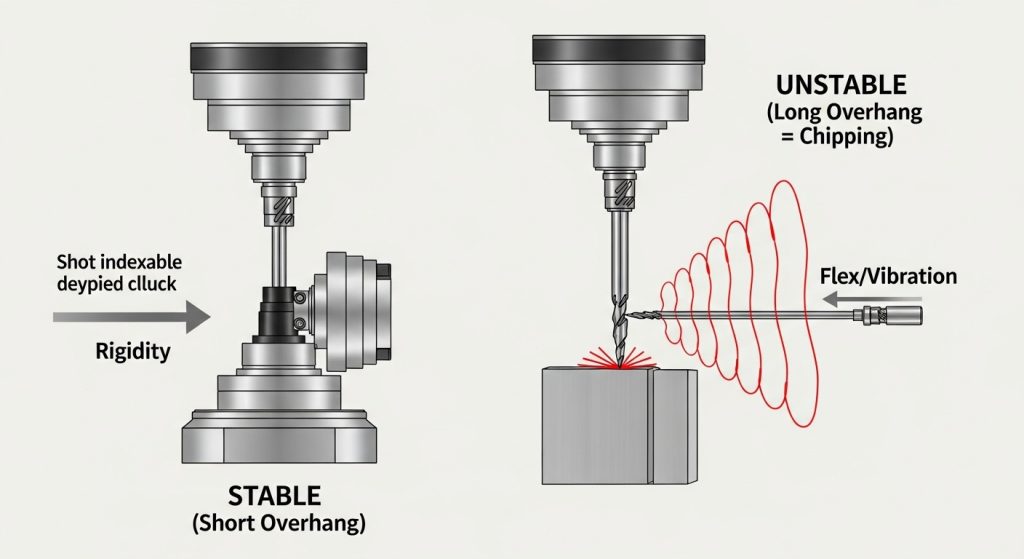
The Overhang Factor
The most common culprit is tool overhang. Every time you double the length-to-diameter ratio (L/D) of a tool, the static stiffness decreases by a factor of eight.
- The Fix: Always use the shortest drill possible for the hole depth.
- Workholding: Ensure the workpiece is rigidly clamped. If the part moves even 0.001″ during the cut, that movement translates to impact load on the insert corner.
Excessive Runout (TIR)
In indexable drilling, the peripheral (outer) insert is the most vulnerable to chipping. This is because it travels at the highest surface speed and defines the hole tolerance.
If your drill has excessive Total Indicated Runout (TIR), the outer insert is not cutting smoothly; it is engaging and disengaging with every rotation. This intermittent cutting action causes immediate corner chipping.
Target Tolerances
For indexable drills, we recommend a maximum runout of 0.002″ (0.05mm).
Pro Tip: If you consistently see chipping on the outer insert, don’t just check the drill. Check your collet, hydraulic chuck, or adapter. A worn sleeve is often the root cause of the runout.
For a deeper dive into maintaining your tool assemblies to prevent these issues, review our industrial drill maintenance and buying guide.
Interrupted Cuts and Uneven Entries
Drilling into a flat, solid surface is straightforward. Drilling into a slanted surface, a weld seam, or through a cross-hole is where chipping thrives.
When a drill enters or exits an uneven surface, the cutting forces become unbalanced. One insert might be fully engaged while the other is cutting air. This imbalance causes the drill to deflect, snapping the brittle carbide edge.
The “Soft Entry” Strategy
You do not need to change your tool for interrupted cuts; you need to change your code.
- Reduce Feed: When entering a slanted surface or breaking into a cross-hole, reduce your feed rate (IPR) by 50% to 70%.
- Spot Drill: If the surface is extremely irregular (like a casting skin), use a spot drill to create a flat pilot for the indexable drill to enter.
Incorrect Grade Selection (Too Hard)
There is an eternal trade-off in carbide engineering: Hardness vs. Toughness.
- Hard Grades (ISO P05-P10): Excellent heat resistance, typically CVD coated. Great for high speed, but brittle.
- Tough Grades (ISO P25-P40): Higher cobalt content, typically PVD coated. Excellent shock resistance, but wears faster.
If you are experiencing chipping, your insert grade is likely too hard for the application. This is common when drilling unstable setups or materials with hard spots.
The Solution: Switch to a “tougher” grade. You may sacrifice some theoretical tool life (due to faster wear), but you will gain process security by eliminating the unpredictable chipping failures.
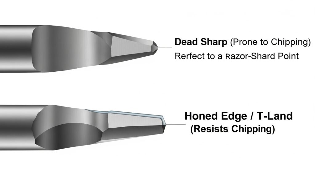
Edge Preparation Matters
Look at the edge of your insert. Is it razor-sharp? A “dead sharp” edge is weak. For steel and iron drilling, we recommend inserts with a Honed Edge (T-Land). This microscopic rounding of the edge reinforces it against the shock of entry.
A Step-by-Step Prevention Checklist
If you are standing at the machine with a chipped insert, follow this troubleshooting hierarchy:
- Inspect the Seat: Remove the insert and look at the pocket. Is it deformed? A damaged seat allows the insert to move.
- Check Center Height: On a lathe, if the drill is slightly below center, the center insert will chip or crush.
- Adjust Feed: High feed rates increase mechanical load. If chipping occurs, reduce the feed (Chip Load per Tooth).
- Verify Coolant: Thermal shock (rapid heating and cooling) can cause “comb cracks” that look like chipping. Ensure coolant flow is continuous and high-pressure.
Conclusion
Chipping is preventable. It is almost always a sign that the mechanical load on the edge has exceeded the carbide’s transverse rupture strength. By maximizing rigidity, controlling runout, and selecting a tougher grade for unstable conditions, you can stop chipping before it starts.
At Accurate Cut, we engineer our inserts with specific substrates and edge preparations to handle these rigorous industrial environments. Don’t settle for tools that chip—optimize your process.
Frequently Asked Questions
What is the difference between chipping and fracture?
Chipping is a localized breakage along the cutting edge (micro-failure), often allowing the tool to keep cutting poorly. Fracture is a catastrophic failure where a large portion of the insert breaks off, usually stopping the operation immediately.
Does coolant pressure affect chipping?
Indirectly, yes. If coolant pressure is too low to evacuate chips, the chips can get trapped and “recut.” This recutting action puts massive mechanical shock on the edge, causing chipping.
Should I increase or decrease speed to stop chipping?
Speed (RPM) is rarely the cause of chipping. Chipping is caused by mechanical force (Feed) or vibration. To stop chipping, leave the speed alone (or match it to the material) and focus on reducing the feed rate or increasing rigidity.
Why do my inserts chip only on the exit?
This is caused by “breakout forces.” As the drill pushes through the bottom of the part, the material thins and tries to push away rather than cut. This sudden release of pressure causes the drill to jump forward (spring back), chipping the edge. Reduce feed by 50% for the last 1mm of the cut.