


How to Select Carbide Inserts for CNC Drilling
There is nothing more frustrating than pulling a drill out of a hole and seeing the body friction-welded to the part because an insert failed catastrophically. It’s the nightmare scenario: you’ve scrapped the part, destroyed an expensive drill body, and now the machine is down while you dig out the mess.
Often, the blame gets put on the feeds and speeds or the coolant pressure. But in our experience at Accurate Cut, the culprit is usually simpler: the wrong insert for the application.
Indexable drilling is a balancing act. Unlike solid carbide drills, which are a single piece of homogenous material, indexable drills rely on the interplay between the drill body and usually two distinct inserts. Choosing the right combination of grade, geometry, and coating isn’t just about buying what’s on sale—it’s about process security.
In this guide, we’re going to walk through the engineering logic behind selecting the correct carbide inserts for CNC drilling, ensuring you get the longest life and the lowest cost per hole.
The Anatomy of Indexable Drilling: It’s a Two-Insert System
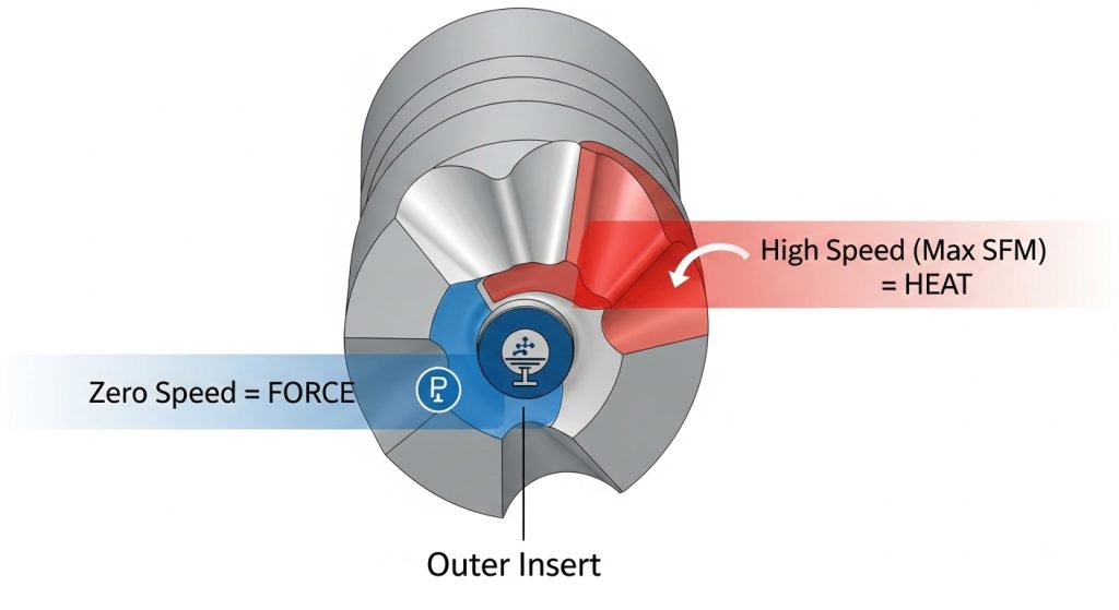
Before diving into grades and coatings, we need to address the mechanics of the tool. Most indexable drills use two inserts: a central (inner) insert and a peripheral (outer) insert.
Many shops make the mistake of putting the same grade in both pockets to simplify inventory. While convenient, this is rarely optimal.
The Peripheral (Outer) Insert:
This insert runs at the maximum surface footage ($V_c$). It generates the most heat and handles the majority of the cutting work.
- Primary Need: Wear resistance and heat tolerance.
The Central (Inner) Insert:
The center of the drill is a unique environment. At the very tip, the surface speed (SFM) is effectively zero. The insert isn’t just cutting; it’s pushing and extruding material.
- Primary Need: Toughness and resistance to chipping.
If you put a hard, wear-resistant grade in the center, it will likely chip due to the low speed and high pressure. If you put a tough, soft grade on the outside, it will burn up rapidly from the heat. Successful selection means balancing these two forces.
Step 1: Analyzing the Workpiece Material (ISO Groups)
The first variable in your selection equation is always the material. In the tooling world, we categorize these by ISO standards. Your choice here dictates the substrate hardness and the coating technology.
ISO P (Steels)
Carbon and alloy steels are the most common, but they vary wildly. For low-carbon, “gummy” steels (like 1018), you need a sharper edge to prevent the material from tearing. For alloy steels (like 4140), heat generation is the enemy.
- Recommendation: Look for CVD coatings (Al2O3) for the peripheral insert to block heat, and PVD coatings for the center to maintain edge toughness.
ISO M (Stainless Steel)
Stainless steel is notorious for work hardening and Built-Up Edge (BUE), where material welds itself to the cutting edge.
- Recommendation: You need sharp, positive geometries here. A honed or blunt edge will cause work hardening instantly. Use PVD-coated grades (TiAlN) that resist chemical affinity with the material.
ISO K (Cast Iron)
Cast iron produces short chips but is highly abrasive. It eats soft grades for breakfast.
- Recommendation: You need thick, hard coatings. Toughness is less of a concern than pure abrasion resistance.
ISO N (Non-Ferrous/Aluminum)
The danger here is aluminum sticking to the insert (galling), which clogs the flutes and snaps the drill.
- Recommendation: Use highly polished, uncoated carbide or DLC (Diamond-Like Carbon) coatings. Never use an Al2O3 coating on aluminum—the aluminum in the coating will chemically bond with the aluminum in the part.
Step 2: Selecting the Right Geometry and Chipbreaker
In turning or milling, a bad chip is annoying. In drilling, a bad chip is fatal. Because the tool is buried inside the hole, the chips must be evacuated immediately. If the geometry doesn’t break the chip into small “C” or “6” shapes, you’ll pack the flutes.
Strong vs. Sharp Geometries
- Strong/Blunt: Use these for interrupted cuts (like drilling through cross-holes) or unstable setups. They push more water but handle abuse better.
- Sharp/Positive: Essential for lower-power machines (CAT40 or smaller) and long-reach drills. They reduce cutting forces and minimize vibration.
The Wiper Geometry
Some peripheral inserts feature a “wiper” flat. This acts like a finishing pass, smoothing out the feed lines on the hole wall. If surface finish is your priority, ensure your outer insert has a wiper facet.
Step 3: Grade and Coating Selection
This is where the science happens. The grade is the combination of the carbide substrate (the tungsten-cobalt mix) and the coating applied on top.
The Substrate Rule of Thumb
- High Cobalt (10-12%): This makes the insert tougher but softer. Use this for the inner pocket or when drilling unstable, stacked plates.
- Low Cobalt (6-8%): This makes the insert harder but more brittle. Use this for the outer pocket or high-speed stable production.
PVD vs. CVD Coatings
Understanding the difference between PVD and CVD is critical for application success.
- PVD (Physical Vapor Deposition): Thin and smooth. It preserves the sharpness of the edge. Ideal for stainless steel, superalloys, and central inserts where edge strength is vital.
- CVD (Chemical Vapor Deposition): Thicker and better at insulating against heat. Ideal for the peripheral insert in steel and cast iron applications where speed is high.
See our full drill insert coatings guide for a deeper dive into specific chemical compositions.
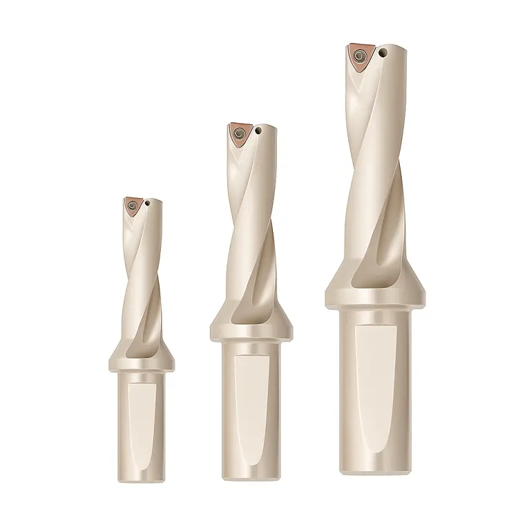
Step 4: Matching Inserts to Drill Length (L/D Ratio)
The length of your drill significantly changes how you should select inserts. A short stub drill acts differently than a long deep-hole drill.
Short Drills (2xD – 3xD)
These are rigid. You can get away with harder, more aggressive grades and higher feed rates. The risk of deflection is low.
Long Drills (4xD – 5xD and up)
Once you go past 4xD, vibration becomes a real threat. If the drill chatters, the brittle carbide inserts will micro-chip.
- Strategy: For long drills, move to a freer-cutting (sharper) geometry to reduce radial cutting forces. Lower cutting forces mean less deflection and less chatter. You may also need to slightly reduce the surface footage (RPM) to protect the outer corners.
The Coolant Factor
For deep indexable drilling, through-coolant is non-negotiable. However, thermal shock is a risk. If you are using a CVD grade and the coolant supply is intermittent, the rapid heating and cooling can cause “comb cracks” on the edge. In these cases, a PVD grade is often more resilient to thermal cycling.
Troubleshooting Common Insert Failures
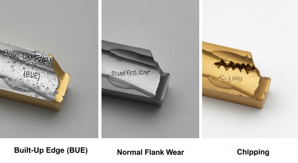
The used insert is a crime scene—it tells you exactly what happened. At Accurate Cut, we always encourage operators to identify wear patterns before throwing the edge away.
- Built-Up Edge (BUE): If the edge looks like it has material welded to it, you are running too slow or the edge is too dull. Solution: Increase speed ($V_c$) or switch to a sharper, PVD-coated insert.
- Flank Wear: This is the normal wear pattern—a smooth abrasive wearing down of the side. Solution: If it happens too fast, move to a harder, wear-resistant grade.
- Chipping at the Center: If the inner insert is snapping near the center. Solution: The grade is too brittle for the zero-speed center. Switch to a tougher, high-cobalt substrate.
- Outer Corner Failure: If the peripheral insert is burned or blown out at the corner. Solution: The speed is likely too high, or the grade lacks heat resistance. Reduce RPM or switch to a thick CVD coating.
Conclusion
Selecting the right carbide insert for CNC drilling isn’t a guessing game. It’s a systematic process of matching the physics of the cut—zero speed at the center, high speed at the edge—to the material science of the insert.
Remember the three pillars of selection:
- Distinguish Roles: Treat the inner and outer pockets as different tools requiring different attributes.
- Respect the Material: Match the coating (CVD vs. PVD) to the ISO group.
- Watch the Chips: If the chips aren’t breaking, the tool body is at risk. Change geometry immediately.
Don’t let a $15 insert ruin a $500 drill body. By taking the time to select the correct grade and geometry, you ensure predictable, profitable production.
Ready to optimize your drilling operations? Explore Accurate Cut’s catalog of high-performance indexable drills and inserts, or contact our technical team for a custom application assessment.
Frequently Asked Questions (FAQ)
Can I use the same insert grade for both the inner and outer pockets?
Technically yes, but it’s rarely optimal. The outer pocket needs heat resistance (hard grade), while the inner pocket needs toughness (soft grade). Using a “universal” grade usually means compromising performance on both ends, leading to shorter tool life.
When should I change my carbide drill inserts?
You should change inserts when flank wear reaches approximately 0.2mm to 0.3mm. Do not wait for the insert to chip or break. Consistent wear allows for predictable tool changes; catastrophic failure can damage the drill body and the part.
What is the best insert coating for drilling stainless steel?
For stainless steel (ISO M), a PVD TiAlN or AlTiN coating is generally best. These coatings are thin and smooth, preventing the sticky stainless material from adhering to the edge (Built-Up Edge) while maintaining the sharpness required to cut freely.
How does L/D ratio affect insert selection?
As the drill gets longer (higher L/D), the setup becomes less rigid. For drills 4xD and longer, you should select “softer” or freer-cutting geometries to reduce cutting forces. High cutting forces on a long drill cause deflection and vibration, which kills carbide life.
Why are my inserts chipping instantly?
Instant chipping usually indicates a lack of stability or toughness. If it’s the center insert, the grade is likely too hard. If it’s the outer insert, check your runout and ensure the workpiece is clamped rigidly. Also, verify you aren’t feeding faster than the chipbreaker can handle.
What is the difference between WCMX and SPMX inserts?
These are standard ISO designations for insert shapes. WCMX is a trigon shape often used for its stability and three cutting edges. SPMX is a square insert offering four cutting edges. The choice depends on the specific drill body design; they are not interchangeable.