







How to Use Indexable Drills on a Lathe: The Definitive Guide
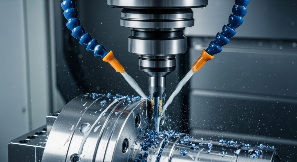
Using indexable drills on a lathe changes your production game entirely. These tools replace standard twist drills to offer higher speeds, better hole finishes, and versatility. You can drill, bore, and even turn with a single tool.
If you want to reduce cycle times and eliminate spot drilling, indexable drills are the answer. However, they require specific setups and rigid operating parameters. This guide covers everything from alignment to X-axis offsets.
What Are Indexable Drills and Why Choose Them?
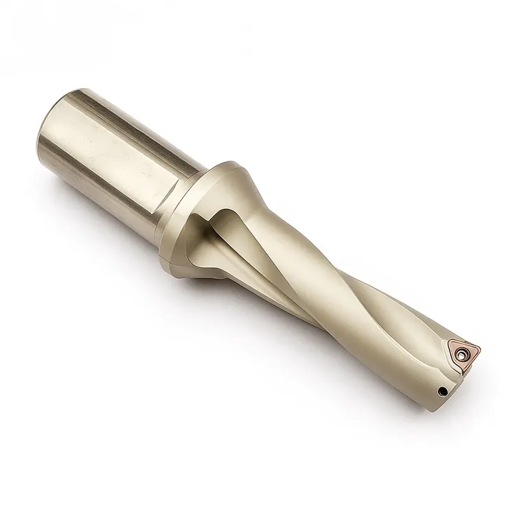
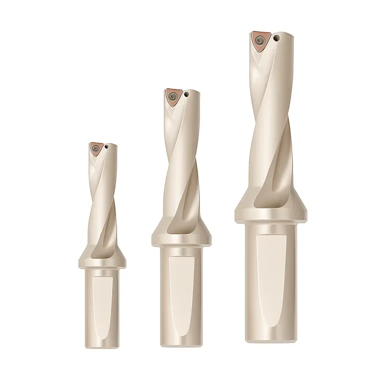
Indexable drills use replaceable carbide inserts instead of a solid steel body to cut metal. They allow for significantly faster material removal rates (MRR) and eliminate the need for spotting operations. Machinists choose them for cost-efficiency, as you simply rotate a worn insert rather than sharpening the entire tool.
The Mechanics of the Tool
Unlike High-Speed Steel (HSS) or solid carbide twist drills, an indexable drill (often called a U-Drill or Insert Drill) typically uses two inserts:
- The Central Insert: Cuts the center of the hole where surface speed is effectively zero.
- The Peripheral Insert: Cuts the outer diameter at full surface speed.
This dual-action design balances the cutting forces. It allows the tool to plow through material like 4140 steel or 316 stainless much faster than traditional tooling.
Key Advantages Over Twist Drills
- No Spot Drilling: The rigid body design prevents walking.
- Cost Effective: Buying inserts is cheaper than replacing large solid carbide drills.
- Versatility: You can use them as a boring bar after drilling the hole.
- Coolant Flow: Through-tool coolant is standard, aiding chip evacuation.
How Critical Is Lathe Setup and Alignment?
Setup is the single most important factor for tool life when using indexable drills. The drill must be perfectly concentric with the spindle centerline to prevent premature failure. Misalignment causes uneven insert wear, oversized holes, and potential tool body destruction.
Achieving Perfect Concentricity
If your turret is off by even 0.002", you are in trouble. The central insert will rub rather than cut. This creates a "pip" at the bottom of the hole or, worse, snaps the drill body.
To ensure you are running true, you need a rigorous alignment process. You must sweep the tool holder with a coaxial indicator.
- Check Radial Alignment: Ensure the X-axis is zeroed perfectly to the spindle center.
- Check Angular Alignment: Ensure the tool is parallel to the Z-axis travel.
If you are struggling with consistent alignment, review our guide on CNC setup optimization. It details how to dial in your turret for maximum rigidity.
Rigidity and Overhang
Indexable drills exert massive axial force. Keep the tool overhang as short as possible. A good rule of thumb is to never exceed a 3:1 length-to-diameter ratio unless you are using a vibration-dampened holder.
Do You Need to Spot Drill Before Using an Indexable Drill?
No, you rarely need to spot drill with an indexable drill on a lathe. These tools are designed to self-center due to their rigid geometry and cutting forces. Skipping the spotting operation significantly reduces cycle time and simplifies the tooling list.
Why Spotting Can Be Detrimental
Actually, spotting can hurt indexable performance.
If you spot drill, you create a pre-existing angle. If that angle doesn't match the indexable drill's point angle perfectly, the peripheral insert might engage before the center insert. This causes chatter immediately upon entry.
The Exception:
The only time you should spot drill is if you are entering a convex or irregular surface (like a casting) where the drill might deflect on contact. Otherwise, trust the tool rigidity and enter the cut confidently.
What Are the Optimal Feeds and Speeds?
Indexable drills thrive on high RPM and aggressive feed rates to stabilize the cut. Generally, run surface footage 3-4 times higher than HSS. Ensure the chip load is heavy enough to break chips, usually starting around 0.004 to 0.012 IPR depending on material.
Calculating Surface Feet Per Minute (SFM)
You cannot be timid with these tools. If you run them too slow, the inserts will rub and chip.
- Mild Steel: Start around 600-800 SFM.
- Stainless Steel (304/316): Aim for 400-550 SFM.
- Aluminum: Push upwards of 1200+ SFM.
For a deeper dive on dialing in your spindle speed relative to material hardness, refer to our RPM setup guide.
The Importance of Feed Rate (IPR)
Feed rate controls chip breaking. This is the "heartbeat" of the operation.
If the feed is too light, you get long, stringy chips. These "bird's nests" wrap around the tool and can destroy the turret.
If the feed is too heavy, you risk fracturing the insert.
Standard Starting Feeds:
| Drill Diameter | Starting Feed (IPR) | Max Feed (IPR) |
| :--- | :--- | :--- |
| 0.500" - 0.750" | 0.003 | 0.006 |
| 0.750" - 1.000" | 0.005 | 0.009 |
| 1.000" - 1.500" | 0.006 | 0.012 |
| 1.500"+ | 0.008 | 0.016 |
If you are seeing long chips, increase your feed rate by 10%. For more precise calculations, check our specific guide on feed rate setup for indexable drills.
How Does Coolant Pressure Affect Performance?
High-pressure through-tool coolant is non-negotiable for indexable drilling on a lathe. It evacuates chips from deep holes and keeps inserts cool to prevent thermal cracking. Without adequate pressure, chips pack in the flutes, leading to catastrophic tool failure.
The Role of Chip Evacuation
In a vertical mill, gravity helps remove chips. On a lathe, you are drilling horizontally. Gravity is useless here. You rely entirely on coolant velocity to flush chips out of the hole.
- Minimum Requirement: 150 PSI is the baseline.
- Ideal Pressure: 300 to 1000 PSI is preferred for holes deeper than 3x Diameter.
If you hear a crunching sound, hit the E-Stop. That is the sound of chips re-cutting. Re-cutting chips destroys insert coatings instantly.
Can You Adjust Hole Size Without Changing the Tool? (Offsetting)
Yes, you can adjust hole diameter by offsetting the drill in the X-axis on a lathe. Moving the drill slightly off-center allows you to bore a larger hole or fine-tune tolerances without swapping the tool body.
The "Magic" of X-Axis Shifts
This is a feature unique to lathes. Because the workpiece rotates, you can treat the drill like a boring bar.
- To Drill Larger: Shift the drill in the X-axis towards the peripheral insert.
- To Drill Smaller: You generally cannot drill smaller than the nominal diameter. You will rub the drill body.
Example:
If you have a 1.000" drill but need a 1.015" hole, you don't need a boring bar. Simply offset the X-axis by roughly 0.0075" (depending on your machine's radial vs. diametric programming).
Warning: Do not offset too far. If the central insert crosses the centerline, you will lose the cutting action at the center, leaving a "nub" that will smash the tool.
How Do You Troubleshoot Common Issues?
Listen for chatter and inspect chips immediately to troubleshoot indexable drilling issues. Long, stringy chips indicate poor feed rates, while loud screeching suggests insert failure or misalignment. Check insert screws for tightness and ensure coolant is flowing correctly before restarting.
Diagnostic Table
Use this quick reference to solve problems on the shop floor:
| Symptom | Probable Cause | Solution |
| Long Stringy Chips | Feed rate too low | Increase Feed (IPR) by 10-20%. |
| Loud Screeching | Worn inserts or lack of rigidity | Rotate inserts; Check overhang length. |
| Vibration / Chatter | RPM too high or instability | Reduce RPM; Check CNC setup optimization. |
| Oversized Hole | Drill Misalignment | Re-sweep tool holder concentricity. |
| Drill Body Wear | Chip packing | Increase coolant pressure; Check chip shape. |
If you are consistently struggling with tolerance issues despite good chips, read our analysis on hole accuracy in CNC drilling.
Best Practices for Insert Management
Rotate your inserts before they fail catastrophically to save the drill body. Monitor the wear patterns on the cutting edge. Once the wear land reaches 0.010 inches, index or replace the insert to maintain process reliability.
Peripheral vs. Central Wear
The peripheral insert travels the fastest distance. It usually wears out faster due to heat. The central insert travels slower but deals with "crushing" forces at the center.
Pro Tip:
Many shops use different grades for the two positions.
- Peripheral: Use a tougher, heat-resistant grade (PVD coating).
- Central: Use a grade with high edge strength to resist chipping (CVD coating).
Conclusion: Mastering the Indexable Drill
Using indexable drills on a lathe is a requirement for high-production machining. They offer speed, precision, and flexibility that twist drills cannot match.
By focusing on perfect alignment, aggressive feeds, and proper coolant strategies, you will see a massive ROI. Remember to utilize the X-offset feature to hit tight tolerances without changing tools. Start with the manufacturer's recommended data, but don't be afraid to push the tool. Listen to the cut—it will tell you everything you need to know.
