


How to Improve Chip Control in Stainless Steel: The Definitive Guide
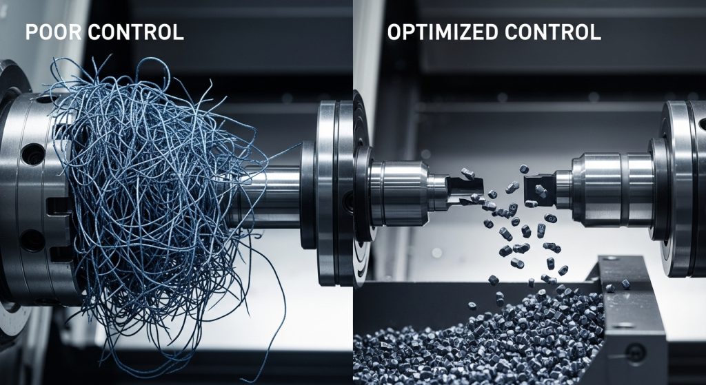
Chip control stainless steel machining is one of the toughest challenges for modern CNC operators. If you ignore chip management, you risk tool failure, poor surface finishes, and dangerous “bird’s nests” that halt production.
This guide covers everything you need to know. We will explore geometry, feed rates, and coolant strategies to master this material.
What Causes Poor Chip Control in Stainless Steel?
Why is stainless steel so difficult to machine?
Stainless steel is problematic because of its high ductility and low thermal conductivity. Instead of breaking cleanly, the material stretches and flows, creating long, stringy chips. It also tends to work-harden rapidly. If you don’t cut aggressively enough, the material hardens, and the chip becomes an unbreakable wire.
The Science of the “Gummy” Cut
In my experience, 300-series stainless (like 304 and 316) acts like gummy candy. It wants to stick to the tool rather than shear off. This leads to Built-Up Edge (BUE).
When BUE occurs, the geometry of your tool changes effectively. The sharp edge dulls. The chip breaker groove gets clogged. Suddenly, you aren’t cutting; you are plowing. This generates immense heat.
To combat this, you must understand the material properties. For a broader look at how different alloys behave, refer to our material-based drilling guides. Understanding the base material is step one.
How Does Feed Rate Affect Chip Breaking?
Is increasing feed rate the best way to break chips?
Yes, increasing the feed rate is often the most effective method to improve chip control in stainless. A higher feed rate generates a thicker chip. Thicker chips are stiffer and less flexible. This added rigidity forces the chip to snap when it hits the chip breaker, rather than curling into a long string.
The “Thick-to-Thin” Principle
You cannot baby stainless steel. Many operators slow down when they hear noise, but that is a mistake. Slowing down causes the tool to rub. Rubbing creates heat and work-hardening.
- Push the Tool: You need to maintain a chip load that exceeds the cutting edge radius.
- Avoid Dwell: Never let the tool dwell in the cut. It glazes the surface immediately.
- Variable Feed: Sometimes, programming a “peck” or a variable feed rate can manually break the chip.
If you are dealing with materials that have already work-hardened due to poor prior processing, the rules change slightly. You can read more on that in our guide on how to drill hardened materials.
Which Insert Geometries Are Best for Stainless Steel?
What specific tool geometry helps break stainless chips?
You need a positive rake angle combined with a dedicated, aggressive chip breaker groove. A positive rake shears the metal cleanly, reducing the heat entering the chip. The chip breaker groove then forces the chip to curl tightly upon itself. This tension causes the ductile stainless to snap into manageable “6” or “9” shapes.
Selecting the Right Breaker
Not all inserts are created equal. For stainless, look for:
- Sharp Cutting Edges: To slice through the gummy structure.
- Polished Rake Faces: To reduce friction and prevent sticking.
- Tight Chip Grooves: To force a tighter curl radius.
Avoid flat-top inserts. They offer no obstruction to the chip flow. You need that physical barrier (the back wall of the chip breaker) to force the break.
Why Is Coolant Strategy Critical for Chip Evacuation?
Does high-pressure coolant actually break chips?
High-pressure coolant (HPC) significantly improves chip control by thermally shocking the chip. The rapid cooling makes the hot chip brittle, causing it to fracture more easily. Furthermore, the hydraulic force of the coolant wedges between the chip and the tool, lubricating the cut and blasting the chip away from the work zone.
Thermal Shock and Lubricity
Stainless holds heat. Since it doesn’t conduct heat well, the heat stays in the cut zone. This creates a thermal nightmare.
- Flood Coolant: Often insufficient. It boils away before reaching the cutting edge.
- Through-Tool Coolant: Essential for drilling. It gets the fluid exactly where the heat is generated.
Managing temperature is vital not just for the chip, but for tool life. If you are struggling with thermal failure, check our article on how to reduce heat when drilling steel.
How Do Tool Coatings Impact Chip Flow?
Can the right coating prevent chips from nesting?
Yes, advanced coatings reduce the coefficient of friction, allowing chips to slide across the rake face efficiently. Coatings like TiAlN (Titanium Aluminum Nitride) or AlTiN create a slippery, heat-resistant barrier. This prevents the chip from welding to the tool (BUE), ensuring it hits the chip breaker groove at the correct speed and angle to snap.
The Role of Friction
If the chip drags on the tool surface, it slows down. This changes the curl. It creates a loose, stringy bird’s nest.
A slick coating keeps the chip moving fast. It hits the breaker wall hard and snaps.
- TiAlN: Excellent for high heat.
- Multi-layer coatings: Provide both toughness and slickness.
Choosing the right layer is a science in itself. For a deep dive into tribology and surface science, review our resource on coating for tough materials.
Troubleshooting Guide: Common Chip Issues and Fixes
What should you do if you still get stringy chips?
If you are seeing long stringy chips, first increase your feed rate by 10-15%. If that fails, increase the Depth of Cut (DOC) to engage more of the chip breaker. If the chips are too tight and breaking the insert, reduce the feed slightly or switch to a tougher insert grade.
Quick-Reference Troubleshooting Table
| Symptom | Probable Cause | Immediate Action |
| Long, continuous string | Feed rate too low | Increase feed rate (Chip Load). |
| Bird’s nesting around tool | Depth of Cut (DOC) too shallow | Increase DOC to engage chip breaker. |
| Built-Up Edge (BUE) | Cutting speed too low / Poor lubricity | Increase speed or upgrade coolant concentration. |
| Insert chipping/fracturing | Chip jamming / Feed too high | Check flute evacuation or reduce feed. |
| Poor surface finish | Recutting chips | Improve coolant pressure to flush chips. |
Step-by-Step: Setting Up Your Machine for Success
How do you set up a CNC machine for stainless steel?
Ensure your setup is as rigid as possible to handle the increased cutting forces required for stainless. Minimize tool overhang (keep runout below 0.0005″). Check your coolant concentration; it should be at least 10-12% for stainless steel to provide adequate lubricity. Finally, verify your spindle power is sufficient for aggressive feed rates.
The Checklist for Operators
- Rigidity: Clamp the workpiece solidly. Vibration kills carbide.
- Tool Runout: Use precision collets or hydraulic chucks.
- Coolant Mix: Use a refractometer. Watery coolant causes BUE.
- Program Check: Verify your speeds and feeds against the tool manufacturer’s data for the specific alloy (e.g., 304 vs. 17-4 PH).
Final Thoughts on Chip Control
Mastering chip control in stainless steel is about balancing forces. You need enough force to shear the metal, but enough finesse to manage the heat.
By optimizing your feed rates, selecting positive geometries, and utilizing high-pressure coolant, you can turn a nightmare job into a profitable run. Remember, a broken chip is a good chip.