


How Indexable Drill Geometry Affects Hole Quality
If you’ve spent enough time on the shop floor, you know the feeling. You’re running a batch of 316 stainless, your speeds and feeds are right out of the catalog, and coolant pressure is good—yet the holes are coming out bell-mouthed, or the surface finish looks like the threads of a bolt.
The immediate reaction is usually to tweak the feed rate or swap out the inserts. But in my experience, 9 times out of 10, the issue isn’t just the cutting parameters; it’s the geometry.
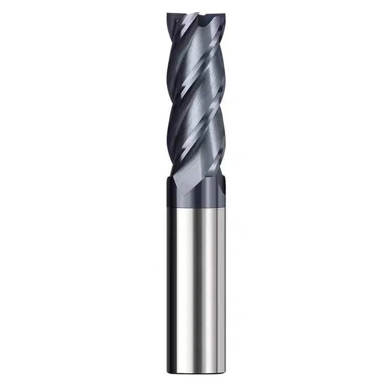
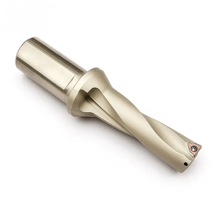
Unlike solid carbide drills that rely on symmetry, indexable drills are a different beast entirely. They are essentially single-effective cutting tools—mechanically more similar to a boring bar than a twist drill. Understanding the physics of how the insert geometry, body design, and force balance interact is the difference between a sloppy IT12 hole and a precision IT9 result.
Here is a deep dive—essentially an advanced indexable drilling guide—into how geometry dictates your hole quality and how to leverage it for better parts.
The Unique Physics of Indexable Drilling
To fix hole quality issues, you first have to understand the “tug-of-war” happening inside the hole.
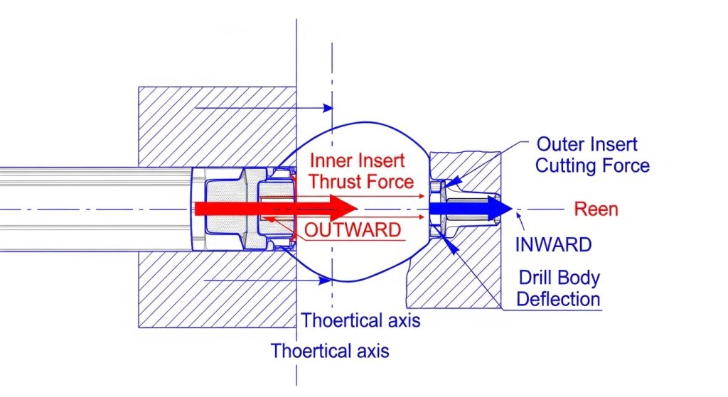
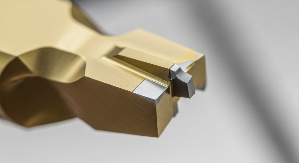
An indexable drill typically uses two inserts: a Central (Inner) insert and a Peripheral (Outer) insert. Since these drills don’t have a chisel edge to center themselves like a twist drill, they rely entirely on the balance of radial forces between these two inserts to drill straight.
The Force Balance Equation
When the drill enters the material, the inner insert hits first (usually). Because it’s cutting near the centerline where surface speed is effectively zero, it generates a massive amount of thrust and pushes the drill body outward.
Milliseconds later, the outer insert engages. Its job is to cut to size and generate a counter-force that pushes the drill body back inward.
If your geometry is “unbalanced”—meaning the chip breaker or rake angle on the inner insert generates significantly more force than the outer one—the drill will deflect. This deflection is what causes:
- Oversized holes: The drill is pushed off-center.
- Tapered walls: The deflection changes as the drill gets deeper.
- Bell-mouthing: Severe deflection at the entry before the tool stabilizes.
Insert Geometry: The Micro-Factors That Matter
You can’t just grab any two ISO inserts and hope for the best. The specific micro-geometry of the inserts plays a massive role in surface finish and tolerance.
Lead Angles and Corner Radii
The lead angle of the insert changes the direction of the cutting forces. A standard 90-degree square insert directs forces radially (sideways). By adjusting this angle or using a larger corner radius, you direct more force axially (up into the spindle).
- High Radial Force: Good for stabilizing the drill in deep holes, but risks deflection if the drill is long (4xD or higher).
- High Axial Force: Reduces chatter but requires a very rigid setup and a high-thrust machine.
The “Wiper” Effect
If you are chasing surface finish (low $R_a$), look closely at your peripheral insert. High-performance geometries often include a small “wiper” flat—a tiny section of the cutting edge that is parallel to the axis of rotation.
This wiper acts like a finishing tool, ironing out the feed lines on the hole wall. I’ve seen shops reduce their surface roughness by half simply by switching to a geometry with a 0.5mm wiper flat, without changing their cycle time or CNC efficiency.
Chip Breakers: Soft vs. Hard Action
Here is a common mistake I see: using the same geometry for both pockets.
- Inner Pocket: Needs a “soft” cutting geometry (high positive rake) because it deals with low surface speeds and shearing forces. It needs to shear the material, not plow it.
- Outer Pocket: Can handle a “harder” geometry (reinforced edge) because it is running at full surface speed and needs to withstand impact and heat.
If you use a heavy-duty roughing geometry in the center pocket, the drill will struggle to penetrate, causing vibration that ruins the wall finish.
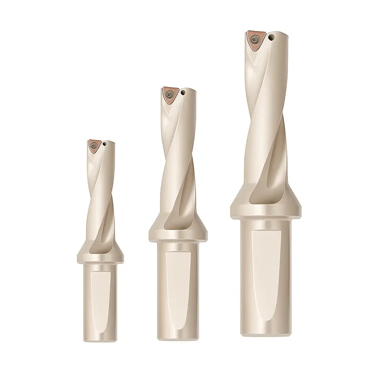
Drill Body Geometry: Stability in the Cut
The inserts do the cutting, but the body does the steering. The rigidity of the body geometry is what translates the insert performance into a round hole.
Flute Design and Core Strength
There is always a trade-off here. Large, wide flutes are great for chip evacuation (essential for aluminum or gummy steels), but they remove mass from the tool body. A thinner core means less rigidity.
For high-tolerance holes, you generally want a drill body with:
- Helical Flutes: These help pull chips out naturally, reducing the chance of chip packing which scores the hole walls.
- Maximized Core Thickness: A stiffer body resists the radial deflection caused by the insert forces we discussed earlier.
Marginal Width
The “margin” is the cylindrical strip on the drill body that occasionally contacts the hole wall to guide the tool.
- Too narrow: The drill has no support and wanders, creating oval holes.
- Too wide: You get excessive friction and heat, which can work-harden the material surface.
Troubleshooting Common Defects via Geometry
When things go wrong, don’t guess. Use the hole defect to diagnose the geometry failure.
The Hole is Oversized
- Likely Cause: The outer insert is cutting too aggressively, or the drill body is deflecting outward.
- The Fix: Check the runout. If runout is fine, switch to an inner insert with a freer-cutting (sharper) geometry. This reduces the outward push, bringing the drill back to the center line.
Bell-Mouthing at Entry
- Likely Cause: The drill is “walking” before it stabilizes. This is common with flat-bottom geometry or unbalanced insert forces.
- The Fix: Reduce the feed rate by 50% during entry (first 2-3mm). If that fails, use a pilot drill or a spot drill with a matching angle to guide the initial cut.
Poor Surface Finish (Rifling Marks)
- Likely Cause: Chatter. The drill is vibrating at a natural frequency.
- The Fix: This is counter-intuitive, but sometimes you need to increase the feed rate to load the tool and stop the bouncing. Alternatively, switch to a peripheral insert with a larger corner radius or a specialized wiper geometry.
Accurate Cut’s Perspective: Beyond the Standard Catalog
We talk a lot about geometry, but I have to be honest about the limitations. You can have the most advanced geometry in the world, but if your tool holding is sloppy, it won’t matter.
At Accurate Cut, we often see that “geometry issues” are actually “rigidity issues.” Indexable drills exert massive side loads. Using a side-lock holder is standard, but for high-precision work, a hydraulic chuck or a high-torque power milling chuck often yields better roundness because it dampens vibration.
Furthermore, when standard L/D ratios (like 3xD or 5xD) aren’t enough, or when you need to combine drilling and chamfering to save cycle time, that’s where custom tooling solutions come into play. Sometimes the “correct” geometry doesn’t exist in a catalog—it has to be engineered for your specific part.
Frequently Asked Questions
Why do indexable drills typically cut slightly oversized?
Indexable drills are designed with a slight clearance to prevent the body from binding in the hole. Additionally, because they are single-effective tools, the deflection forces often result in a hole tolerance of roughly +0.1mm to +0.2mm. If you need tighter tolerances (H7 or H8), you should be reaming or boring after drilling.
Can I use different insert grades for the inner and outer pockets?
Absolutely, and you often should. The inner insert needs toughness to handle low speeds and shearing forces (e.g., a PVD grade). The outer insert needs wear resistance to handle high heat and speed (e.g., a CVD grade). Mixing grades optimizes tool life and hole quality.
How does the L/D ratio affect geometry requirements?
As the Length-to-Diameter (L/D) ratio increases, stiffness decreases. For deep hole drilling (5xD or greater), you need freer-cutting geometries to reduce radial pressure. You must also reduce feeds significantly to prevent the drill from bowing in the cut.
What causes the “pip” or nub at the bottom of the hole?
This is a geometric necessity. Because the inner insert must overlap the center line to cut, and the outer insert trails behind, the bottom of an indexable drill hole is rarely perfectly flat. It usually has a distinct profile or “W” shape depending on the lead angles.
Why is my drill screeching?
Screeching is the sound of high-frequency chatter. It usually means the tool isn’t cutting; it’s rubbing. Check if your peripheral insert’s flank is worn, or if your feed rate is too low. A drill needs to be pushed hard enough to stabilize the cut and dampen the vibration.
The Bottom Line
Drilling holes seems simple until you have to hold a tight tolerance. While it’s tempting to blame the operator or the machine, the reality is often hidden in the geometry of your tooling.
The interplay between the inner and outer inserts creates a dynamic force balance. If you get that balance right—using the correct chip breakers, lead angles, and wiper flats—you can achieve remarkable consistency. If you ignore it, you’ll be fighting chatter and runout all day.
If you are struggling with difficult materials or specific industry requirements, standard catalog items might not cut it. Explore Accurate Cut’s range of high-performance solutions to find the geometry that fits your specific production reality.