


What Insert Geometry Works Best for Drilling
There is nothing worse than the sound of a drill screeching halfway through a deep hole. The machine vibration creates that tell-tale “chatter” on the surface finish, and you know the tool life is plummeting by the second.
When this happens, the immediate reaction on the shop floor is usually to back off the feed rate or slow down the spindle. But in many cases, the speeds and feeds aren’t the culprit. The problem is the insert geometry.
Using a “one-size-fits-all” insert for every job is a recipe for work hardening, poor hole tolerances, and catastrophic tool failure. The geometry that shears through 304 Stainless Steel like butter will shatter instantly if applied to Cast Iron.
At Accurate Cut, we know that drilling is unique compared to turning or milling because chip evacuation is the primary limitation. If the geometry doesn’t break and eject the chip, the drill fails. This guide breaks down exactly how to match insert geometry to your material and why the difference between your central and peripheral inserts matters more than you think.
Understanding Drilling Geometry: It’s More Than Just Shape
When we talk about “geometry” in drilling, we aren’t just talking about the physical dimensions of the carbide. We are talking about the engineering features designed to control chip formation and reduce cutting forces.
To choose the right insert, you need to understand three core variables:
- The Rake Angle: This is the angle of the cutting face relative to the workpiece. A positive rake is sharp and “scoops” the material, reducing cutting forces. A negative rake is flatter and stronger, pushing material away but requiring more horsepower.
- The Chipbreaker: These are the ridges and grooves molded into the top of the insert. Their sole job is to curl the chip until it snaps, allowing it to flush out of the flute.
- Edge Preparation (Honing): A razor-sharp edge is actually weak. Most drilling inserts have a “hone” or “T-land” (a microscopic rounded or chamfered edge) to prevent chipping. The size of this hone changes based on the material.
It is also vital to understand how your coating interacts with the geometry. For a deeper dive, read our drill insert coatings guide.
Quick Summary:
- Soft/Sticky Material (Alum, Stainless): Needs Positive Rake + Sharp Edge + Tight Chipbreaker.
- Hard/Abrasive Material (Iron, Hardened Steel): Needs Negative/Flat Rake + Heavy Hone + Open Chipbreaker.
The Critical Split: Central vs. Peripheral Inserts
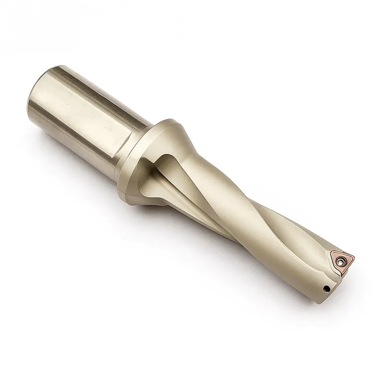
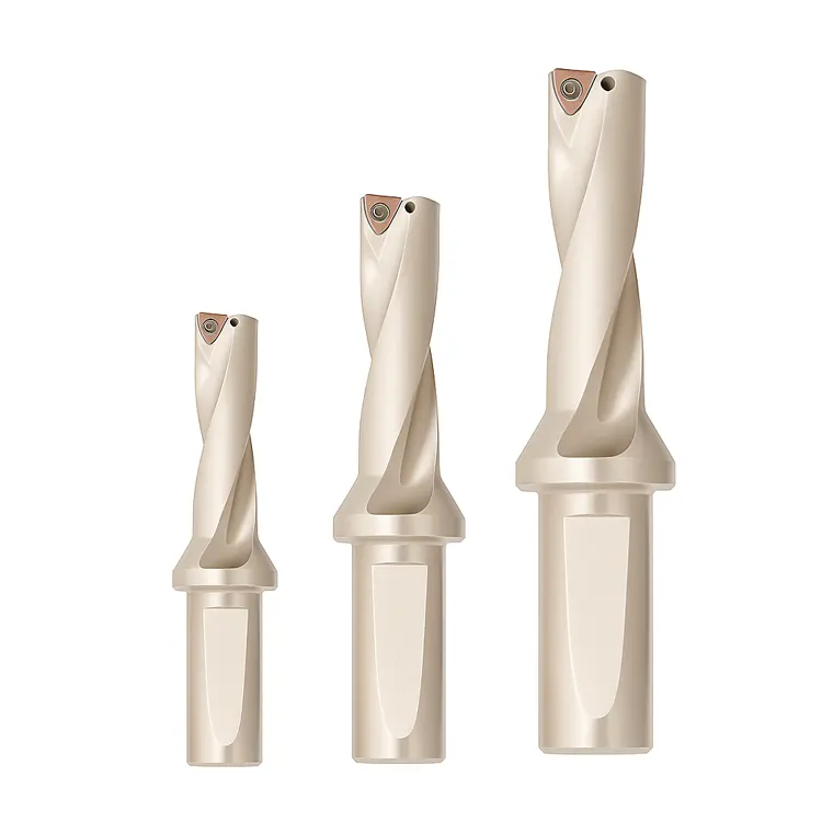
If you look closely at a modern indexable drill (like a 2D or 4D insert drill), you will notice the pockets are often different shapes. Even if they take the same size insert (e.g., WCMX or SPMG), the role of those inserts is completely different.
This is where many operators make a costly mistake: assuming the inner and outer inserts do the same job.
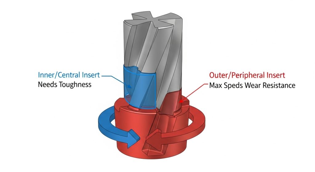
The Central (Inner) Insert
The very center of a drill has a surface speed (SFM) of effectively zero. It doesn’t “cut” as much as it punches and extrudes material.
- Requirement: Extreme Toughness.
- Geometry: The central insert needs a geometry that can handle shock and low speeds without chipping. It often uses a slightly softer grade with a stronger edge prep.
The Peripheral (Outer) Insert
The outer corner of the drill is moving at maximum SFM. It faces high heat and abrasive wear.
- Requirement: High Wear Resistance.
- Geometry: The peripheral insert needs a geometry designed to withstand heat. It usually utilizes a harder grade and a geometry that manages corner wear.
Pro Tip: If you are mixing up your grades or geometries, you will likely see the outer insert burning up while the inner insert chips. Always check the manufacturer’s guide to see if your drill body requires specific “Inner” vs. “Outer” geometries.
Best Geometries by Material Application
The “universal” drill insert is a myth. While some multi-material grades exist, optimizing for production requires matching the geometry to the ISO material group.
Geometry for Steel (ISO P)
Carbon and alloy steels are the most common materials drilled, but they vary wildly in hardness. To go deeper into specific grades for this material, check out our guide on the best drill insert for steel.
- Ideal Geometry: Look for a balanced design. You want a moderate positive rake to keep cutting forces manageable, combined with a medium edge hone to protect against shock.
- Chipbreaker: An open groove design usually works best here to create “6” or “9” shaped chips that evacuate easily.
- Goal: Predictable wear and consistent chip control.
Geometry for Stainless Steel & High-Temp Alloys (ISO M & S)
Stainless steel (like 304/316) and Superalloys (Inconel/Titanium) are notorious for work hardening. If the tool rubs instead of cuts, the material hardens instantly, and the next rotation of the drill destroys the insert. Finding the best drill insert for stainless steel is critical here.
- Ideal Geometry: You need a High Positive geometry. The edge must be sharp.
- Edge Prep: Avoid heavy hones. You need a “light” hone or a sharp edge to shear the material cleanly.
- Chipbreaker: These materials produce long, stringy chips. You need an aggressive, tight chipbreaker to snap the chip immediately.
- Warning: Do not dwell. If the drill stops feeding, the geometry will polish the hole, and you will likely lose the drill.
Geometry for Cast Iron (ISO K)
Cast iron doesn’t produce long chips; it produces powder or short flakes. It is also highly abrasive.
- Ideal Geometry: You need strength. A Negative or flat geometry is preferred.
- Edge Prep: A heavy T-land (chamfer) or heavy hone is critical. A sharp edge will chip instantly upon hitting the hard “crust” of cast iron.
- Chipbreaker: Since the chips break naturally, the chipbreaker is less about curling and more about reducing crater wear on the insert face.
Geometry for Aluminum (ISO N)
The enemy here is Built-Up Edge (BUE), where the aluminum welds itself to the cutting edge.
- Ideal Geometry: Extremely sharp, High Positive rake.
- Surface: Polished surfaces are mandatory. Uncoated, polished carbide prevents the aluminum from sticking.
- Chipbreaker: A “lasered” or sharp breaker that ejects chips rapidly to prevent clogging the flutes.
Visualizing Success: Reading Your Chips

The drill creates the hole, but the chips tell the story. You cannot see inside the hole while drilling, so you must learn to read the chips flying out of the conveyor. Learning how to identify drill insert wear patterns and chip shapes is a key skill for any machinist.
- The Perfect Chip: Look for small, tight “C” shapes (often called 6s and 9s). This means the geometry is breaking the material efficiently, and the heat is leaving with the chip.
- The “Bird’s Nest”: If you see long, stringy ribbons wrapping around the tool, your geometry is too free-cutting (not enough obstruction) or your feed rate is too light. You need a tighter chipbreaker geometry.
- The “Needles”: If the chips are tiny, splintered needles, the geometry might be too aggressive (negative) for the material, causing it to shatter rather than shear. This often leads to chatter.
Common Mistakes in Geometry Selection
Even experienced machinists can get tripped up by the nuances of modern insert technology. Here are the top mistakes we see in the field:
Ignoring the Wiper Flat
Some drilling inserts come with a “wiper” geometry—a small flat section on the periphery. This acts like a tiny finishing tool, smoothing out the feed lines. If your surface finish requirements are high, ensure your outer insert has a wiper geometry. If you are just blasting rough holes, a standard radius is stronger.
Using Steel Geometry on Stainless
This is the most common cause of failure. A standard steel insert usually has a hone that is too dull for stainless. It generates excessive heat, work-hardens the hole walls, and results in a scream that every machinist dreads. Always switch to an ISO M/S specific geometry for stainless.
Confusing Grade with Geometry
Remember, the “Grade” is the carbide substrate and coating (e.g., PVD TiAlN), while the “Geometry” is the physical shape. It is vital to choose the right drill insert grade to compliment your geometry. You can have the right grade (heat resistant) but the wrong geometry (too dull), and the tool will still fail. You must get both right.
Additionally, understanding the difference between PVD and CVD coatings can help you match the right surface treatment to your chosen geometry for maximum insert coating tool life.
Conclusion
Choosing the best insert geometry for drilling isn’t about buying the most expensive insert; it’s about understanding the physics of your specific application. The right geometry lowers cutting forces, controls chips, and drastically reduces machine downtime.
If you are cutting Steel, aim for balance. If you are cutting Stainless, prioritize sharpness. If you are cutting Iron, prioritize strength. And always respect the difference between the center and the periphery of your drill.
At Accurate Cut, we specialize in high-performance tooling solutions that help manufacturers reduce cost-per-hole. If you are struggling with chip control or premature tool failure, it might be time to re-evaluate your geometry.
Check out our full range of Indexable Drills and Inserts to find the exact match for your next production run.
Frequently Asked Questions
What is the best insert geometry for stainless steel?
For stainless steel, you need a positive geometry with a sharp cutting edge and a polished or smooth coating. This reduces cutting forces and prevents work hardening. Avoid inserts with heavy hones or negative rake angles, as they generate too much heat.
Can I use the same insert for the center and outside pocket?
It depends on the drill body design, but generally, it is better to optimize. Use a tougher, shock-resistant grade/geometry for the center (where speed is low) and a wear-resistant, harder grade for the periphery (where speed is high).
What does “positive geometry” mean in drilling?
Positive geometry means the cutting edge is angled to “scoop” or shear the material, rather than push it. It requires less machine horsepower and generates less heat, making it ideal for softer or stickier materials like aluminum and stainless steel.
How do I stop long stringy chips when drilling?
Long chips (bird-nesting) usually mean the material isn’t being forced to break. You can fix this by increasing your feed rate (to push the chip harder into the breaker) or by switching to an insert geometry with a tighter, more aggressive chipbreaker.
Does insert geometry affect hole tolerance?
Yes. An insert that creates excessive cutting forces (like a negative geometry used on soft material) can cause the drill to deflect or “walk,” leading to oversized or tapered holes. A wiper geometry on the peripheral insert can significantly improve hole diameter consistency and surface finish.