


How to Choose Correct RPM for Drilling: The Definitive Guide
Your rpm setup determines if you make money or scrap parts. Run too slow, and you waste valuable time. Run too fast, and you burn up expensive carbide.
I have stood in front of CNC machines for decades. I have seen drills shatter because the operator guessed the speed. Drilling is not just about making a hole. It is about chip evacuation, heat management, and cycle time.
This guide covers everything you need to know. We will look at the math, the material science, and the practical “feel” of drilling. We will move beyond basic charts and get into the physics of cutting.
What is the Correct RPM Setup for Drilling?
The correct RPM setup relies entirely on the relationship between Surface Feet per Minute (SFM) and the diameter of your tool. You calculate it using the formula: RPM = (SFM × 3.82) / Tool Diameter. Harder materials generally require lower RPM, while softer materials like aluminum allow for much higher speeds to prevent built-up edge.
Understanding the “Why” Behind the Speed
Many operators confuse RPM (Revolutions Per Minute) with Cutting Speed (SFM). They are not the same.
Think of it this way. A small drill bit has to spin much faster to cover the same amount of ground as a large drill bit. If you run a 1/8″ drill at the same RPM as a 1″ drill, the small drill is barely working.
The goal of your rpm setup is to maintain a consistent cutting edge temperature. Heat is the enemy.
- Too Fast: Friction generates heat faster than the chip can carry it away. The cutting edge softens and fails.
- Too Slow: The material tears rather than cuts. This creates poor surface finish and can work-harden materials like stainless steel.
You must find the “Sweet Spot.” This is where the tool cuts efficiently, and the heat ejects with the chip.
How Do I Calculate RPM Manually?
To calculate RPM manually, you must first identify the manufacturer’s recommended Surface Feet per Minute (SFM) for your material. Then, multiply that SFM by 3.82 (a constant derived from Pi). Finally, divide that result by the drill diameter in inches. For metric setups, use RPM = (Cutting Speed in m/min × 1000) / (π × Diameter in mm).
The Math Made Simple
You don’t need to be a mathematician. You just need a calculator and this formula:
$$RPM = \frac{SFM \times 3.82}{Tool Diameter}$$
Let’s break down a real-world example.
Imagine you are drilling mild steel. The tool manufacturer suggests 100 SFM. You are using a 0.500″ (1/2 inch) drill.
- SFM: 100
- Constant: 3.82
- Diameter: 0.5
Math: $100 \times 3.82 = 382$.
Divide: $382 / 0.5 = 764$.
Your target is 764 RPM.
Pro Tip: If you are unsure, start 10% lower than the calculated number. It is safer to increase speed later than to burn a drill immediately.
Common SFM Baselines (HSS Tooling):
| Material | Estimated SFM | Notes |
| Aluminum | 200 – 300+ | Very forgiving. High RPMs preferred. |
| Mild Steel | 90 – 110 | Standard baseline. |
| Stainless (304) | 40 – 60 | Work hardens easily. Keep feeding! |
| Tool Steel (D2) | 30 – 50 | Requires rigid setup. |
| Titanium | 20 – 40 | Generates massive heat. |
Note: Carbide tooling usually runs 2x to 4x faster than these HSS numbers.
How Does Tool Material Affect RPM?
Tool material changes your rpm setup drastically; carbide drills can run 200% to 400% faster than High-Speed Steel (HSS). HSS is flexible but has low heat resistance, requiring lower speeds. Cobalt bridges the gap, allowing slightly higher speeds in tough alloys. Solid carbide is brittle but extremely heat resistant, demanding high RPM and rigid setups.
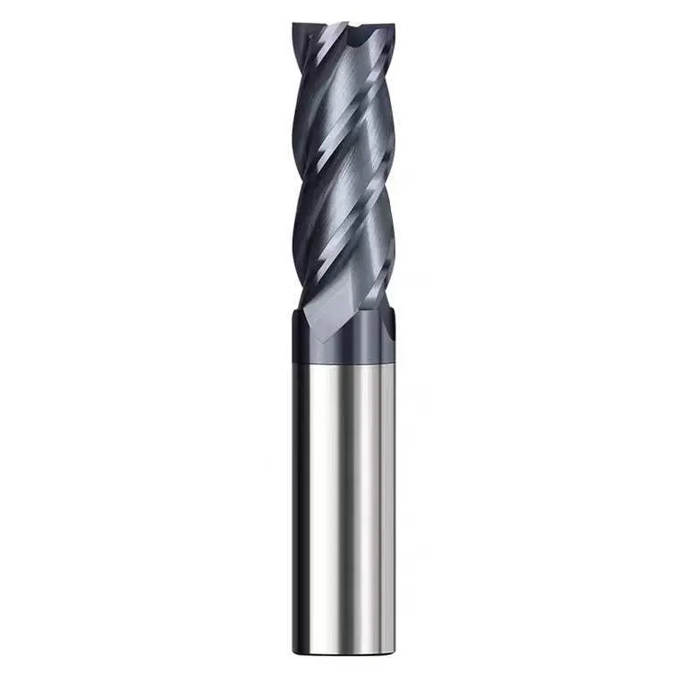
Carbide vs. HSS: The Speed Gap
If you switch from HSS to Carbide without changing your program, you are wasting money.
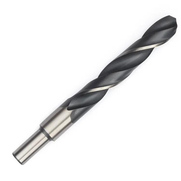
High-Speed Steel (HSS):
These are the standard black or silver bits in most shops. They are tough. They can handle vibration. However, they cannot handle heat. If you run them too fast, the corners round over instantly.
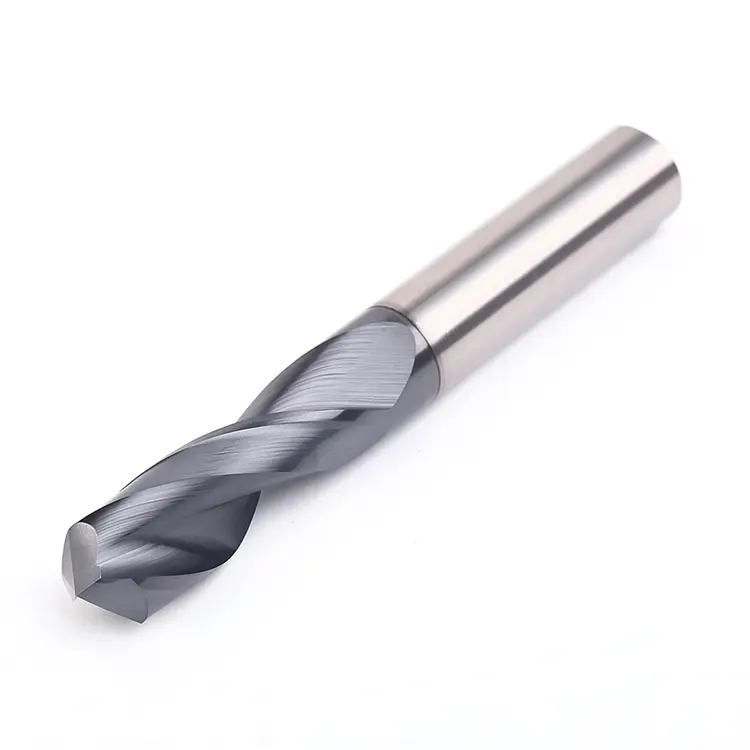
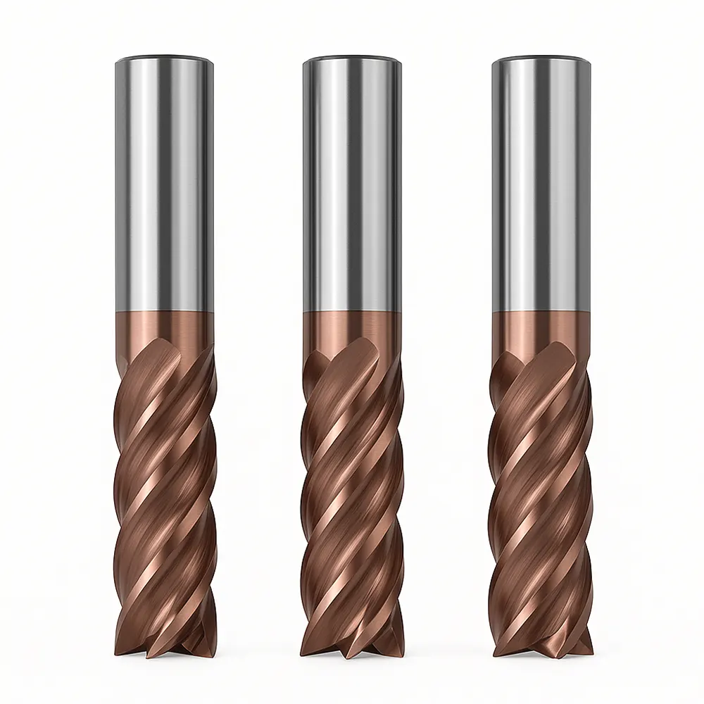
Solid Carbide:
Carbide loves speed. In fact, running carbide too slow can cause it to chip. Carbide relies on speed to plastify the metal slightly at the shear zone. This makes cutting easier.
When upgrading to carbide, you must also look at your feed rates. A high RPM needs a matching feed to prevent rubbing. For a deeper dive into balancing these factors, check our guide on balancing feed rates for indexable drills.
How Does Material Hardness Dictate Speed?
Material hardness dictates speed inversely; as material hardness (Rockwell C) increases, your RPM must decrease. Soft materials like aluminum allow for high RPM to prevent the material from gumming up the flutes. Hard materials like Inconel require very low RPM to reduce heat generation. Ignoring hardness leads to immediate work hardening and drill failure.
The Hardness Factor
Think of drilling into wood versus drilling into concrete.
Soft Materials (Aluminum, Brass, Plastic):
Here, the danger isn’t heat from friction; it’s the material melting. If you run too slow, aluminum can stick to the cutting edge. This is called “Built-Up Edge” (BUE). To stop this, we increase the RPM. This flings the chips away and keeps the flute clear.
Hard Materials (Stainless, Inconel, Titanium):
These materials resist cutting. They generate intense heat at the point of contact. If you run high RPM here, you are essentially friction welding. You must slow down.
The “Screaming” Test:
If your drill is screaming (a high-pitched whine), your RPM is likely too high.
If your machine is rumbling or groaning, your RPM might be okay, but your feed is too heavy.
A good rpm setup sounds like a consistent, low hum.
Does Drill Length Affect RPM?
Yes, drill length significantly affects RPM; longer drills (over 5x diameter) require reduced speeds to prevent whipping and vibration. A standard jobber drill can run at full calculated RPM. However, extra-long “aircraft” drills or deep-hole gun drills often require starting slow to enter the pilot hole, then ramping up. Vibration kills tool life.
The Stability Issue
A short, stubby drill is rigid. You can push it hard.
A long drill acts like a guitar string. It wants to vibrate.
The Rule of Thumb for Deep Holes:
- 3xD Depth: Run at 100% calculated RPM.
- 5xD Depth: Reduce RPM by 10-20%.
- 10xD+ Depth: You need a pilot hole. Do not start a long drill at full RPM outside the hole. It will whip, bend, and snap.
For complex setups involving long tools and deep pockets, you need to ensure your entire machine configuration is solid. You can learn more about optimizing your CNC setup to handle these difficult operations.
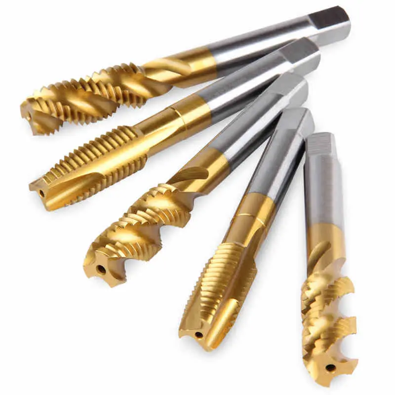
How Do Coatings Change the RPM Setup?
Coatings allow for higher RPM setups by adding a thermal barrier and reducing friction between the chip and the tool. Titanium Nitride (TiN) allows for a 20% speed increase over uncoated tools. Advanced coatings like TiAlN (Titanium Aluminum Nitride) thrive in high heat, allowing for 50-100% higher RPMs in dry machining applications.
Choosing the Right Coat
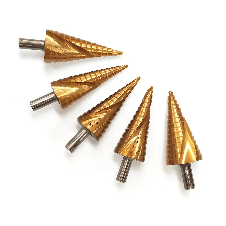
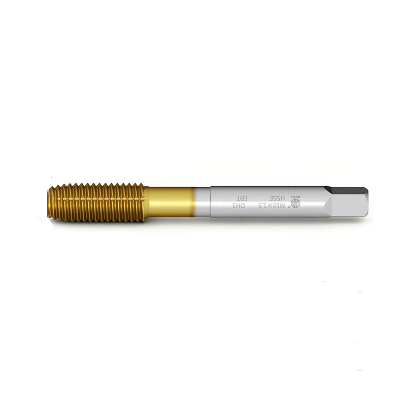
A gold-colored TiN drill isn’t just for looks. That coating is slick. It helps chips slide up the flute.
- Uncoated (Bright Finish): Good for aluminum and plastics. Sharpest edge.
- TiN (Gold): General purpose. Allows slightly higher speed. Good for mild steel.
- TiAlN (Dark Grey/Violet): High performance. This coating actually gets harder as it gets hot. It is perfect for running high RPMs in steel and stainless.
Warning: Never use TiN (Gold) coatings on Aluminum. The aluminum has a chemical affinity to the titanium and will weld itself to the tool.
Quick Troubleshooting: RPM Related Failures
| Symptom | Probable RPM Cause | Solution |
| Outer Corners Burned | RPM Too High | Reduce Speed by 30%. Check Coolant. |
| Chipping at Center | RPM Too Low | Increase Speed. Check Center Height. |
| Loud Squealing | RPM Too High | Reduce Speed immediately. |
| Rough Surface Finish | RPM Too Low / BUE | Increase Speed to shear chip cleanly. |