


Why Drill Inserts Break and How to Prevent It
Experiencing premature drill insert failure? Our guide diagnoses the 7 most common causes—from chip evacuation to runout—and provides engineering-grade solutions to stop breakage.
The true cost of a broken drill insert isn’t just the $15 carbide tip. It’s the downtime required to change it, the potential damage to a $400 drill body, and the risk of scrapping a high-value component.
In the machining world, indexable drilling is often treated as a “roughing” operation, leading some shops to ignore the finer details of setup. However, indexable drills are sophisticated tools that rely on a delicate balance of mechanical force, thermal management, and chip evacuation. When that balance tips, failure follows.
At Accurate Cut, we’ve analyzed thousands of failed inserts. We have found that 90% of catastrophic failures aren’t caused by “bad tools,” but by specific, identifiable errors in parameters or application. This guide goes beyond basic advice to look at the physics of why inserts break and how you can engineer those failures out of your process.
The Dynamics of Indexable Drilling
To prevent breakage, we first need to understand the unique environment an indexable drill operates in. Unlike a turning tool that cuts in open air, a drill is buried inside the material.
Indexable drills typically use two inserts:
- The Center Insert: Operates at near-zero surface footage (SFM) at the very center. It effectively “pushes” material rather than shearing it initially.
- The Peripheral (Outer) Insert: Runs at maximum SFM. It handles the highest thermal load and defines the hole diameter.
Because these two inserts experience vastly different forces, they often fail for different reasons. Understanding which one is breaking is your first clue to solving the problem.
Analyzing Wear Patterns: What Your Insert is Telling You
Before you adjust a single feed or speed, you must look at the failed insert under magnification. The “dead” insert is essentially a black box recorder of the failure.
Here are the most common failure modes and their root causes:
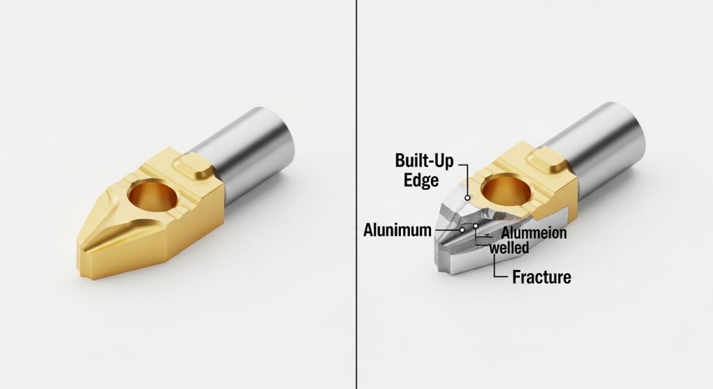
1. Built-Up Edge (BUE)
This occurs when material welds itself to the cutting edge. It is rampant in “gummy” materials like aluminum, low-carbon steel, and stainless steel. The welded material alters the geometry of the tool, eventually causing the edge to chip away.
- The Cause: Cutting speed (SFM) is too low, or coolant concentration is insufficient (lacking lubricity).
- The Fix: Increase your surface footage to generate enough heat to plasticize the chip flow, or increase coolant concentration to 10-12%.
2. Rapid Flank Wear
If the abrasive wear on the side of the insert happens too quickly, you are simply burning the tool up.
- The Cause: Cutting speed is too high for the material hardness.
- The Fix: Reduce RPM. If productivity is a priority, switch to a harder, more wear-resistant carbide grade (typically a thicker coating).
3. Thermal Cracking (Comb Cracks)
These look like small spider-web cracks perpendicular to the cutting edge. They are caused by rapid heating and cooling cycles (thermal shock).
- The Cause: Intermittent coolant supply or widely fluctuating temperatures (common in milling strategies, less common in continuous drilling).
- The Fix: Ensure consistent, high-pressure coolant flow. Paradoxically, running dry (with air blast) is sometimes better than running with weak, intermittent coolant.
4. Chipping at the Corner
This is a fracture, not wear. It indicates mechanical instability.
- The Cause: Excessive feed rate (chip load), runout, or vibration.
- The Fix: Check the Total Indicated Runout (TIR) of the tool and reduce feed rates.
The Silent Killer: Chip Evacuation
In our experience, chip evacuation is the number one cause of catastrophic drill body destruction.
When a drill goes deep (3xD or greater), chips must be flushed out of the flutes immediately. If they aren’t, they get “recut.” This means the drill is trying to cut solid metal and loose hardened chips simultaneously. The pressure spikes instantly, and the insert—or the drill body—snaps.
Critical Prevention Steps:
- Fluid Pressure: For indexable drills, volume is good, but pressure is king. We recommend a minimum of 300 PSI for deep hole applications.
- Coolant Inducers: Ensure the coolant holes in the drill body aren’t clogged with sludge or fines.
- Read the Chips: Look at your chip conveyor.
- Short “6s” and “9s”: Ideal.
- Long Stringers: Dangerous. They wrap around the tool. Increase feed rate to break chips.
- Dust/Powder: Feed is too light; you are rubbing.
Machine Stability and Runout
You cannot hold tight tolerances or get good tool life if the drill is wobbling. Indexable drills are generally more rigid than solid carbide, but they have limits.
Runout (TIR)
If your drill has a runout greater than 0.002″ (0.05mm), the peripheral insert will take an uneven, “hammering” load every rotation. This leads to corner chipping.
- Check the Turret: On CNC lathes, a misalignment between the spindle centerline and the turret station is a common culprit.
- Check the Adapter: Are you using a worn sleeve or collet?
The “Fear Factor”: Why Slowing Down Can Be Worse
When an operator sees sparks or hears a loud noise, their instinct is often to slow the feed rate down. In many cases, this is exactly the wrong move.
Metal cutting relies on shearing. To shear metal cleanly, the tool must penetrate the material.
- The Danger of Rubbing: If you feed too lightly (e.g., 0.001 IPT), the insert edge rubs against the material rather than cutting it. This generates immense heat and work-hardens the material surface.
- The Result: The next time the insert passes, it hits a hardened “glaze,” causing immediate failure.
The Rule of Thumb: Maintain the manufacturer’s recommended chip load. If you need to reduce cutting forces, reduce the speed (RPM), not the feed.
Inspecting the Drill Body (The Pocket)
Sometimes, you put a fresh insert into a drill, and it breaks within five parts. Why?
The problem often lies in the pocket (seat) of the drill body. If a previous failure damaged the seat, the new insert will not sit flat. Even a gap of 0.001″ allows the insert to micro-vibrate. Under cutting pressure, the carbide—which is brittle—will snap because it isn’t supported from behind.
Our Recommendation: Inspect the pocket under a loupe every time you change inserts. If the seat is deformed or washed out, replace the drill body. Using a compromised body is a quick way to burn through expensive inserts. For more comprehensive strategies on tool care, please refer to our industrial drill maintenance and buying guide.
Conclusion
Insert breakage is rarely a mystery; it is a symptom of a mechanical or thermal imbalance. By learning to read the wear patterns—distinguishing between thermal cracks, built-up edge, and fracture—you can isolate the root cause.
Remember the hierarchy of troubleshooting:
- Stability: Is the setup rigid and runout-free?
- Evacuation: Are chips getting out of the hole?
- Parameters: Are we cutting (shearing) or rubbing?
At Accurate Cut, we provide high-performance drilling solutions designed to handle the rigors of modern manufacturing. If you are struggling with consistent tool failure, don’t guess—analyze.
Frequently Asked Questions
Why do my drill inserts break as soon as they touch the part?
This usually indicates a severe stability or setup issue. Check that the part face is flat (not angled) and that the drill is perfectly centered. If entering an uneven surface, reduce the feed rate by 50% until the drill is fully engaged.
Can I use the same insert grade for both the center and peripheral pockets?
It depends on the manufacturer, but often, no. The center insert needs toughness (to handle low speed/high force), while the peripheral insert needs wear resistance (to handle high speed/heat). Using a hard, brittle grade in the center often leads to breakage.
What is the optimal coolant pressure for indexable drills?
While you can drill with standard flood coolant (approx. 50-100 PSI) for shallow holes (2xD), we strongly recommend high-pressure through-tool coolant (300-1000 PSI) for holes 3xD or deeper to ensure chip evacuation.
How do I know if my feed rate is too high?
Listen to the machine. A high-pitched screech usually means speed is too high or the tool is dull. A low, heavy rumble or “groan” often indicates excessive feed pressure. Also, monitor your spindle load meter; a sudden spike indicates the tool is being pushed beyond its limit.
Why does stainless steel keep destroying my inserts?
Stainless steel (ISO M) has a tendency to work-harden. If you dwell, pause, or feed too lightly, the material hardens instantly. You must maintain a constant, aggressive feed to stay “under” the hardened skin. Ensure your coolant concentration is high (10%+) to provide lubricity.