


What Affects Hole Accuracy in CNC Drilling? The Definitive Guide
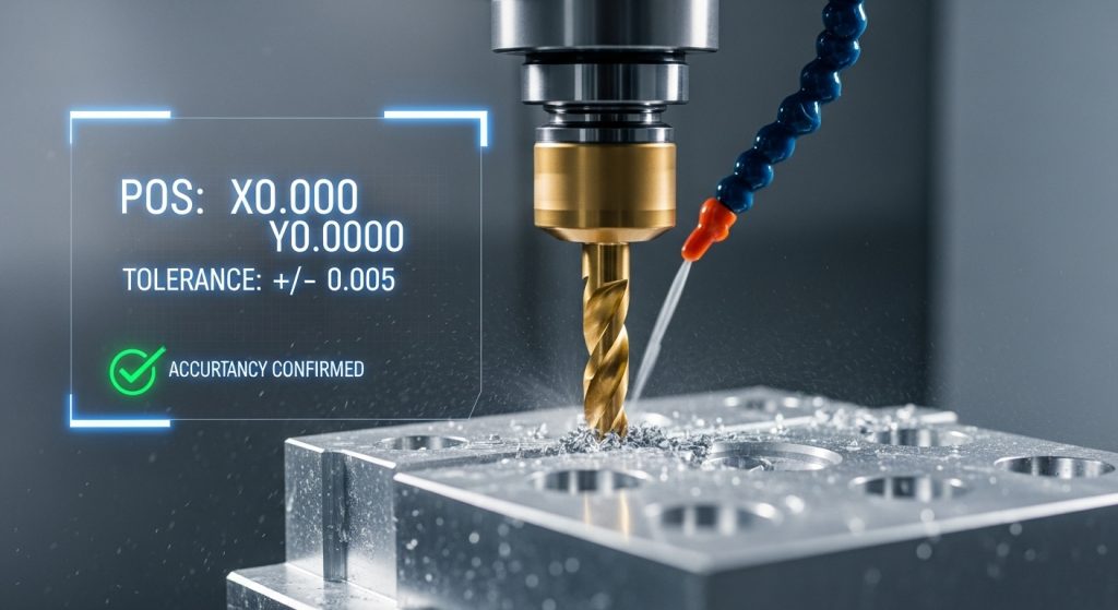
Hole accuracy in CNC drilling is the single most critical metric separating a profitable production run from a bin full of scrap metal. When you are chasing tight tolerances—whether it is position, diameter, or roundness—understanding the variables at play is not just academic; it is essential for survival in a modern machine shop. If you cannot hold tolerance, you cannot ship parts. This guide breaks down exactly what impacts your drilling precision and how to fix it.
What Are the Primary Factors Influencing Hole Accuracy?
Quick Answer: The primary factors affecting hole accuracy in CNC drilling are tool runout, machine rigidity, improper cutting parameters (feeds and speeds), and poor chip evacuation. Secondary factors include the drill’s length-to-diameter ratio, workholding stability, and the thermal expansion of the material during the cutting process.
The Ecosystem of Precision
Achieving a perfect hole isn’t about fixing one thing; it’s about balancing a system. I have walked into shops where operators were blaming the carbide drill manufacturer for oversized holes, only to find their collets were packed with fines from six months ago.
To troubleshoot accuracy, you must look at the “Trinity of Drilling”:
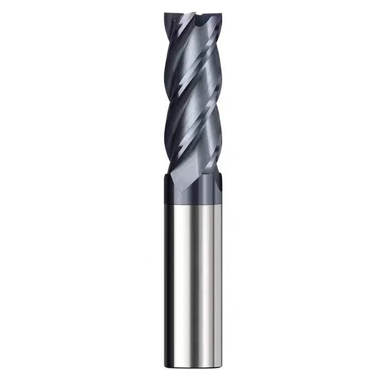
- The Tool: Geometry, runout, and wear.
- The Machine/Setup: Spindle health, fixture rigidity, and alignment.
- The Process: Feeds, speeds, and coolant application.
If any leg of this stool wobbles, your hole tolerance fails.
How Does Tool Runout Affect Drilling Tolerances?
Quick Answer: Tool runout is the leading cause of oversized holes in CNC drilling. If a drill rotates off-center, it acts like a boring bar, cutting a hole larger than the drill diameter. Generally, a hole will be oversized by approximately twice the amount of the runout present at the drill tip.
Understanding T.I.R. (Total Indicated Runout)
Runout is the enemy of precision. In my experience, if you are struggling with holes that are consistently bell-mouthed or oversized, 90% of the time, the issue starts at the spindle nose.
When a drill spins, the tip should rotate perfectly on the centerline. If it wobbles, even by 0.001″ (0.025mm), the drill creates a larger path.
Common Causes of Runout:
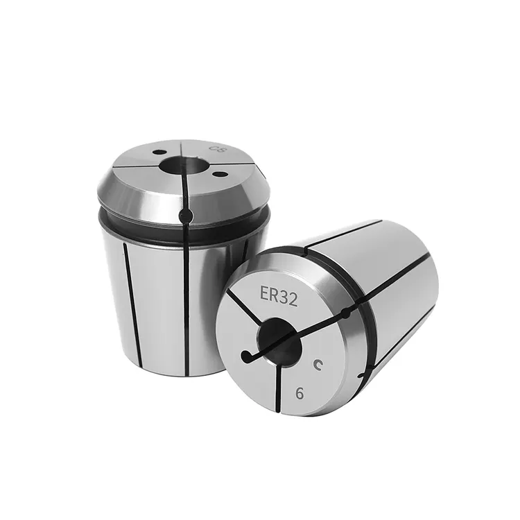
- Dirty Collets: A single metal chip trapped in a collet can throw a tool out by several thousandths.
- Worn Tool Holders: Fretting corrosion inside the taper of your tool holder prevents it from seating perfectly in the spindle.
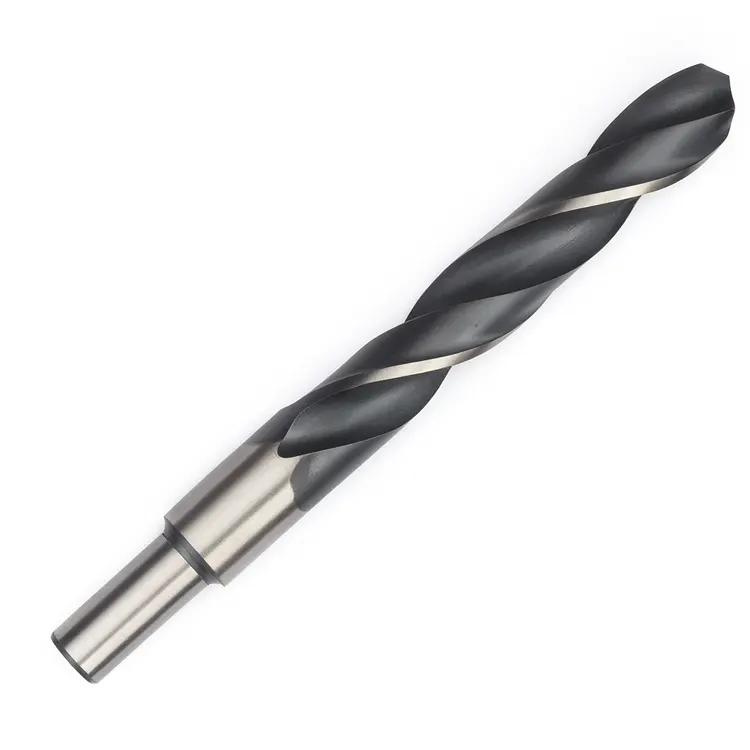
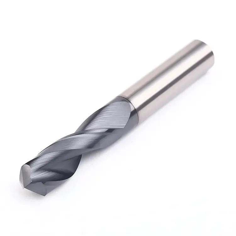
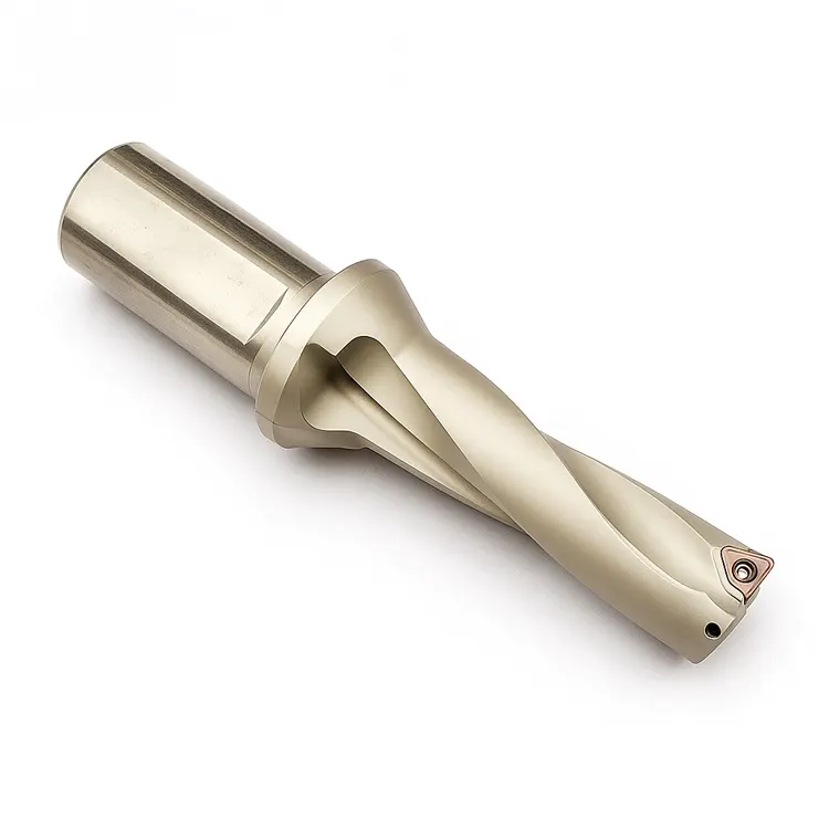
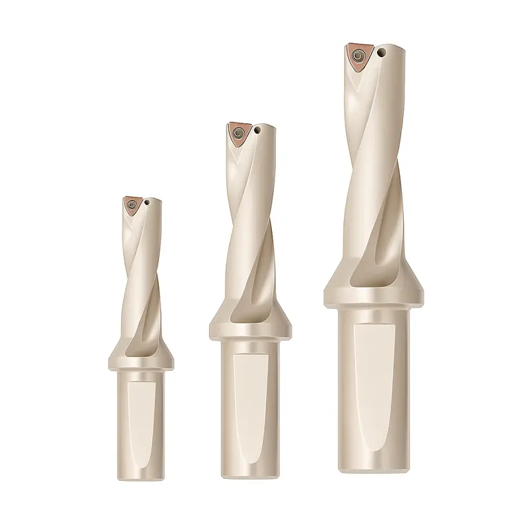
- Poor Quality Drills: Not all carbide is ground equal. Cheaper drills often have inconsistent web thickness.
The Multiplier Effect:
The longer the drill, the worse the runout becomes. A drill with 0.0005″ runout at the holder might have 0.003″ runout at the tip if it is a 10xD drill. This is why checking runout at the tip of the tool, not just the shank, is vital.
| Runout Amount (at tip) | Likely Hole Outcome |
| 0.0002″ | High precision, tight tolerance hold. |
| 0.0010″ | Oversized hole, potential chatter marks. |
| 0.0030″+ | Severely oversized, bell-mouthed entry, likely tool breakage. |
Why Do Feed Rates and Speeds Impact Hole Straightness?
Quick Answer: Improper feed rates directly cause tool deflection and hole wandering. If the feed is too heavy, the drill may buckle under the thrust load, causing the hole to drift off-axis. Conversely, excessive RPM generates heat, causing thermal expansion of the material and resulting in undersized holes once the part cools.
Balancing the Parameters
Many operators guess at their parameters. However, physics dictates that every material has a “sweet spot.”
The Danger of High Feed Rates
When you push a drill too hard, you increase the axial thrust force. On a long drill, this force seeks the path of least resistance. If the spot drill was slightly off, or the surface is uneven, the drill will walk. This creates a hole that is technically the right diameter but is out of position or crooked.
For a deeper dive into managing this specifically with indexable tooling, you should review our guide on feed rate setup for indexable drills. Indexable drills behave differently than solid carbide, and getting the chip load wrong there is a recipe for disaster.
The Heat Factor (RPM)
Speed generates heat. If you run too fast without adequate coolant, the workpiece heats up and expands. You drill the hole to the correct size while hot. When the part cools down, the metal contracts, and your 0.500″ hole shrinks to 0.499″, scraping the part. Always consult a reliable RPM setup guide to match your surface footage (SFM) to the material hardness.
How Does Spot Drilling Improve Hole Location?
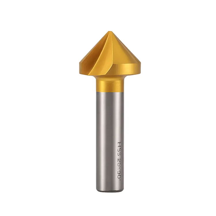
Quick Answer: Spot drilling creates a precise chamfer that guides the tip of the subsequent drill, preventing “walking” upon entry. For high-accuracy holes, the spot drill angle should be equal to or slightly larger than the point angle of the main drill to ensure the drill tips engage the material smoothly and centrally.
The Mechanics of the Start
The most critical moment in drilling is the first contact. If the chisel edge of the drill hits a flat surface, it skids. This skidding puts the hole out of position immediately.
Best Practices for Spotting:
- Angle Matching: If you are using a 140° carbide drill, do not use a 90° spot drill. The tips will touch the outer edges of the spot first, causing chatter and chipping the corners of your expensive drill. Use a 142° or 145° spotter.
- Dwell Time: Do not dwell at the bottom of a spot drill operation. It work-hardens the material, making it harder for the following drill to penetrate.
Table: Spot Drill Compatibility
| Main Drill Angle | Recommended Spot Angle | Why? |
| 118° (HSS) | 120° | Ensures tip centers first. |
| 135°/140° (Carbide) | 142° – 150° | Prevents corner chipping on the main drill. |
| Flat Bottom | Pilot Hole Req. | Flat bottom drills usually require a pilot, not just a spot. |
Does Machine Rigidity and Setup Affect Hole Roundness?
Quick Answer: Yes, machine rigidity and setup stability are fundamental to hole roundness. If the workholding allows the part to vibrate, or if the machine spindle has backlash, the resulting hole will often be oval or “egg-shaped” rather than perfectly round. Vibration acts as an interruptive cut, destroying surface finish and geometry.
The Foundation of Accuracy
You cannot drill a precision hole on a sloppy setup. I have seen machinists try to hold tolerances of +/- 0.0005″ while holding the part in a vice with only 1/8″ of jaw grip and no parallels. The part vibrates, the drill chatters, and the hole ends up looking like a stop sign under a microscope.
Check Your Machine Health:
- Spindle Bearings: Listen to your machine. A whine or growl indicates bearing wear. Bad bearings mean the tool is orbiting, not spinning true.
- Backlash: If your machine hasn’t been calibrated recently, axis reversal errors will show up as oval holes, especially during circular interpolation or helical boring.
For a comprehensive look at ensuring your machine is ready for precision work, refer to our CNC setup optimization guide. It covers the essential checks you need to make before hitting the green button.
How Does Chip Evacuation Impact Hole Surface Finish?
Quick Answer: Poor chip evacuation leads to chip recutting, which scours the walls of the hole and ruins the surface finish. In deep hole drilling, packed chips increase torque and heat, leading to work hardening of the hole walls and potential tool breakage.
The Importance of Coolant Pressure
Chips need to get out of the way. If they don’t, they pack into the flutes. Eventually, the flutes fill up, and the drill acts like a solid rod being forced into the material.
- Through-Spindle Coolant (TSC): This is the gold standard. High-pressure coolant blasts chips out of the hole from the bottom up.
- Peck Drilling: If you don’t have TSC, you must use a peck cycle (G83). However, excessive pecking can hurt tool life. Retracting the tool allows coolant to enter, but it also allows chips to fall back in.
- Chip Shape: You want small “6s” and “9s” (tightly curled chips). If you are getting long stringy nesting birds, your feed rate is likely too low to break the chip.
Conclusion: The Path to Perfect Holes
Hole accuracy in CNC drilling is not luck; it is a calculated result of controlling variables. By minimizing tool runout, calculating precise feeds and speeds, ensuring rigid workholding, and managing chip evacuation, you can hold tight tolerances consistently.
Remember, a drill is only as good as the setup it runs on. Don’t ignore the fundamentals. Check your runout, verify your parameters, and secure your workpiece. Your scrap bin will stay empty, and your profitability will rise.