


How to Avoid Chatter During Indexable Drilling: The Definitive Guide
Chatter is the enemy of precision manufacturing. It kills tool life, ruins surface finishes, and damages machine spindles. When you hear that distinct, screaming vibration during a cut, you know money is being wasted.
In my years on the shop floor, I’ve seen operators panic when chatter starts. They usually turn the feed rate dial down. This is often the wrong move. With indexable drills, hesitation causes failure.
This guide covers exactly how to eliminate vibration. We will look at rigidity, cutting parameters, and tool geometry. We will stop the noise and save your inserts.
What Causes Chatter in Indexable Drilling?
Chatter is a self-excited vibration generated by the interaction between the cutting tool and the workpiece, often caused by a lack of rigidity or incorrect harmonic frequencies. In indexable drilling, this typically stems from excessive tool overhang, poor workholding, or running at a specific RPM that matches the machine’s natural frequency.
To solve this, you must identify the root cause. It is rarely just “one thing.” It is usually a combination of forces.
The Mechanics of Vibration
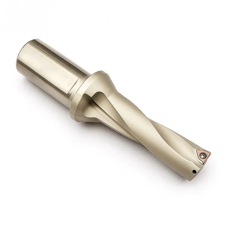
Indexable drills are unique. Unlike twist drills, they often use unbalanced cutting forces because the inner and outer inserts engage the material differently.
- Deflection: The drill body bends slightly under load.
- Regeneration: The tool hits a wavy surface left by the previous revolution, amplifying the wave.
- Mode Coupling: Vibration moves in two directions simultaneously.
If you ignore these mechanics, you cannot fix the problem.
Expert Note: I once troubleshooted a setup running a 5xD indexable drill. The operator kept lowering the RPM. The chatter got worse. We increased the feed rate by 20% to “load” the tool, and the vibration vanished instantly. Stability often requires cutting pressure.
How Does Setup Rigidity Impact Drilling Stability?
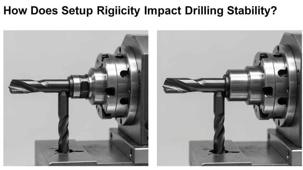
Rigidity is the single most critical factor in preventing chatter; any looseness in the spindle, toolholder, or fixture will amplify vibrations immediately. To ensure stability, you must minimize the distance from the spindle nose to the cut and ensure the workpiece is immovable.
If your setup is weak, no amount of programming magic will save you. You must build a solid foundation.
Optimizing the Workholding
You cannot drill a stable hole in a moving part. Check your hydraulic pressure. Ensure your jaws are bored correctly.
For a deeper dive into stabilizing your entire machine environment, read our CNC Setup Optimization Guide. A rigid setup absorbs energy rather than reflecting it back into the tool.
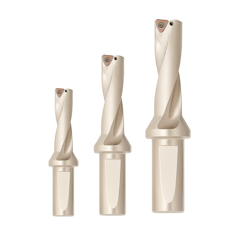
The Tool Overhang Rule
The further your drill sticks out, the less rigid it becomes. Stiffness decreases by the cube of the length.
- 3xD: Very stable.
- 5xD: Requires care.
- 8xD+: Requires a pilot hole and reduced parameters.
Always use the shortest drill possible for the job.
Which Toolholders Are Best for Stopping Chatter?
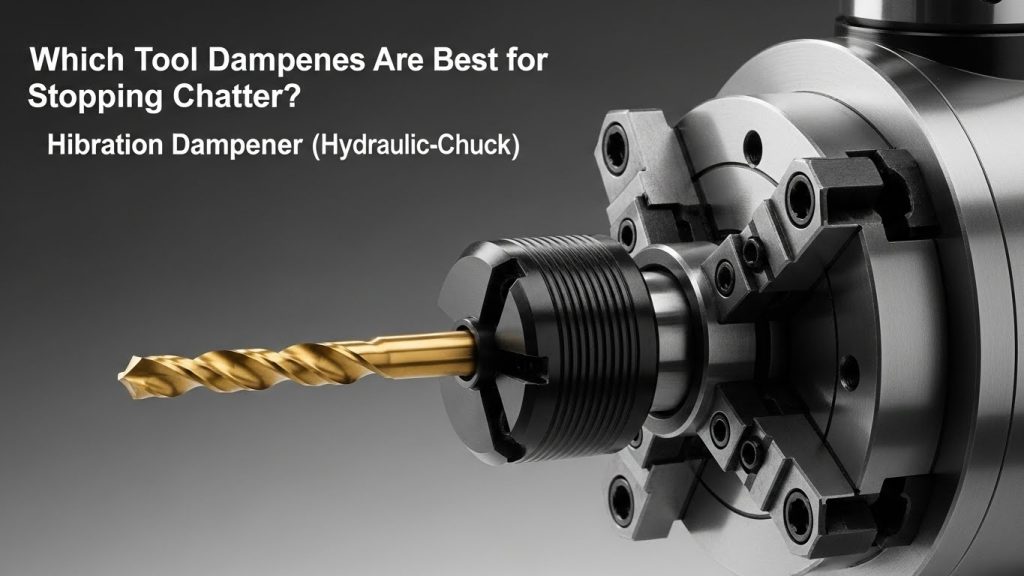
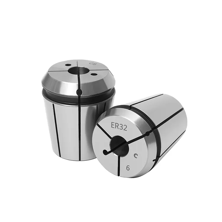
Hydraulic chucks and side-lock (Weldon) holders are superior for indexable drilling because they offer high gripping force and vibration dampening properties. While collet chucks are versatile, they often lack the rigidity required to handle the unbalanced radial forces of an indexable drill.
Choosing the right interface is not just about holding the tool. It is about dampening the harmonic frequency.
Hydraulic vs. Side-Lock
- Side-Lock (Weldon): Provides a positive lock. The tool cannot pull out. However, the set screw pushes the tool off-center, potentially causing runout.
- Hydraulic Chucks: Offer excellent concentricity. The oil inside the chambers acts as a natural vibration damper.
If you are struggling with runout causing vibration, review our guide on the Best Toolholders for Indexable Drills. The right holder acts as a shock absorber.
Can Adjusting Feeds and Speeds Eliminate Chatter?
Yes, altering the RPM changes the harmonic frequency of the cut, while increasing the feed rate stabilizes the tool by directing forces axially into the spindle. Often, chatter occurs because the tool is “rubbing” rather than cutting, so increasing the feed rate is a common and effective solution.
Many machinists fear increasing the feed when they hear noise. You must overcome this instinct.
The “Harmonic Sweet Spot”
Every assembly has a natural frequency. If your cutting frequency matches it, you get resonance (chatter).
- Change RPM: +/- 10% is usually enough to break the harmonic cycle.
- Increase Feed: Push the tool harder. This stabilizes the drill body against the hole wall.
Pro Tip: Don’t just guess. Use a “chatter test.” Vary the spindle speed override by 5% increments while cutting. You will often find a specific RPM where the drill runs silent.
Why Is Chip Evacuation Critical for Vibration Control?
Poor chip evacuation causes chips to re-cut and jam between the drill body and the hole wall, creating immense pressure that results in vibration and tool breakage. If the coolant pressure is too low or the flute geometry is incorrect for the material, chips pack and destabilize the cut.
Silent cutting requires smooth flow. If you hear crunching, chatter is next.
Managing Coolant and Flow
High-pressure coolant (through-spindle) is mandatory for indexable drills deeper than 3xD. It blasts chips out of the hole.
- Pressure: Aim for 300 PSI minimum.
- Volume: You need volume to carry the heat away.
If chips are packing, the drill will vibrate violently before snapping. Learn how to diagnose flow issues in our article on how to Improve Chip Evacuation in CNC Drilling.
How Does Lathe Alignment Affect Drilling Chatter?
On a lathe, if the drill tip is not perfectly on the center line, the unbalanced forces will cause immediate chatter and poor hole tolerance. Even a misalignment of 0.005″ can cause the inserts to fight against the material rather than shear it cleanly.
Lathes present different challenges than mills. The work spins, not the tool.
Checking Center Height
If your drill is below center, it creates a “pip” that pushes the drill sideways. If it is above center, the tool rubs.
- Indicate the Turret: Ensure the pocket is concentric with the spindle.
- Check the Pip: Drill a blind hole. If the nub at the bottom is huge, you are off-center.
For specific steps on aligning turret stations, refer to How to Use Indexable Drills on a Lathe.
Do Spindle Dynamics Differ in Machining Centers?
Yes, machining centers often lack the sheer mass of lathe turrets, making the spindle bearing condition and drawbar retention force critical factors in preventing chatter. A loose drawbar allows the toolholder to micro-move within the taper, destroying surface finish.
Mills spin the tool. This introduces runout dynamics that don’t exist on stationary lathe tools.
Spindle Orientation and Load
If you are drilling horizontally, gravity affects chip flow. Vertical mills struggle with chip recutting.
- Taper Contact: Check for fretting on your toolholders. This indicates vibration.
- Retention Knobs: Ensure they are torqued to spec.
To optimize your mill parameters, see our guide on Indexable Drills in Machining Centers.
How Does Hole Accuracy Indicate Chatter Issues?
Chatter almost always results in oversized holes, poor surface finish, and “bell-mouthing” at the entry or exit of the cut. By measuring the hole diameter and inspecting the wall finish, you can diagnose the severity of the vibration and identify which insert (central or peripheral) is failing.
The hole tells the story. Listen to it.
Reading the Surface Finish
- Rifling marks: Indicates harmonic vibration.
- Gouges: Indicates chip jamming.
- Tapered hole: Indicates tool deflection.
If your tolerances are drifting, vibration is the likely culprit. Learn to measure and interpret these defects in our post on Hole Accuracy in CNC Drilling.
Troubleshooting Guide: Quick Fixes for Chatter
Use this table for rapid diagnosis on the shop floor.
| Symptom | Likely Cause | Immediate Solution |
| High-pitched scream | RPM matches harmonic frequency | Reduce or Increase RPM by 10%. |
| Low rumble / Growl | Lack of rigidity / Overload | Check clamping; Reduce Feed slightly. |
| Crunching sound | Chip packing | Increase coolant pressure; Peck (if necessary). |
| Vibration at entry | Uneven surface | Reduce feed by 50% for first 2mm. |
| Vibration at exit | Thin wall instability | Reduce feed by 50% before breakout. |
Summary and Next Steps
Avoiding chatter during indexable drilling isn’t magic. It is physics. You must balance rigidity, speed, and chip flow.
Start by ensuring your setup is solid. Check your tool overhang. If it screams, don’t be afraid to push the feed harder to stabilize the cut.
Ready to upgrade your process?
Review your current toolholders. If you are using collets for high-feed drilling, swap to a side-lock or hydraulic holder. The difference in silence will amaze you.
Frequently Asked Questions
1. What is the main cause of chatter in drilling? The main cause is a lack of rigidity in the setup or tool, combined with incorrect cutting speeds that create harmonic resonance. This vibration self-amplifies if not corrected by altering RPM or feed rates.
2. Should I increase or decrease speed to stop chatter? You should typically change the speed (RPM) to break the harmonic frequency. Often, reducing RPM helps, but sometimes increasing it moves the vibration out of the resonant zone.
3. Does increasing feed rate help with chatter? Yes, increasing the feed rate often helps. It increases the cutting pressure, which stabilizes the drill body against the hole wall and prevents the tool from “rubbing,” which causes vibration.
4. Why do my indexable drills scream when entering the hole? This happens because the drill is not fully supported by the hole walls yet. The uneven forces on the inserts cause deflection. Reduce the feed rate by 50% during the entry until the drill is fully engaged.
5. Are hydraulic chucks better than collets for drilling? Yes, hydraulic chucks are generally better for indexable drilling. They provide superior dampening characteristics (absorbing vibration) and higher gripping force compared to standard ER collet chucks.