


How to Use Indexable Drills in Machining Centers: The Definitive Guide

Mastering Indexable Drills in Machining Centers transforms your shop’s productivity by drastically reducing cycle times and tooling costs. Unlike traditional twist drills, these tools—often called U-drills or insert drills—utilize replaceable carbide inserts to cut at higher speeds and feeds. This guide covers setup, programming, offsets, and troubleshooting to help you drill with confidence.
What are indexable drills and why use them in machining centers?
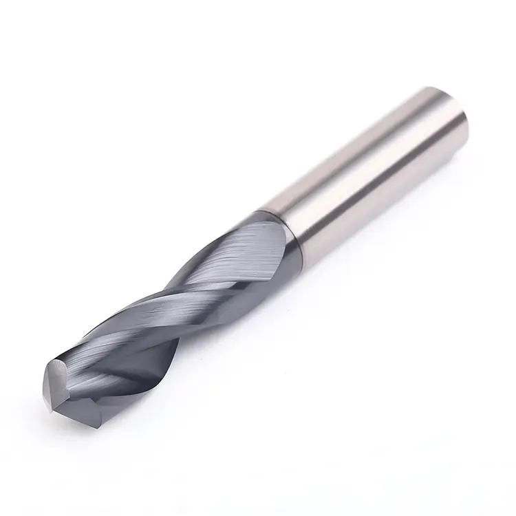
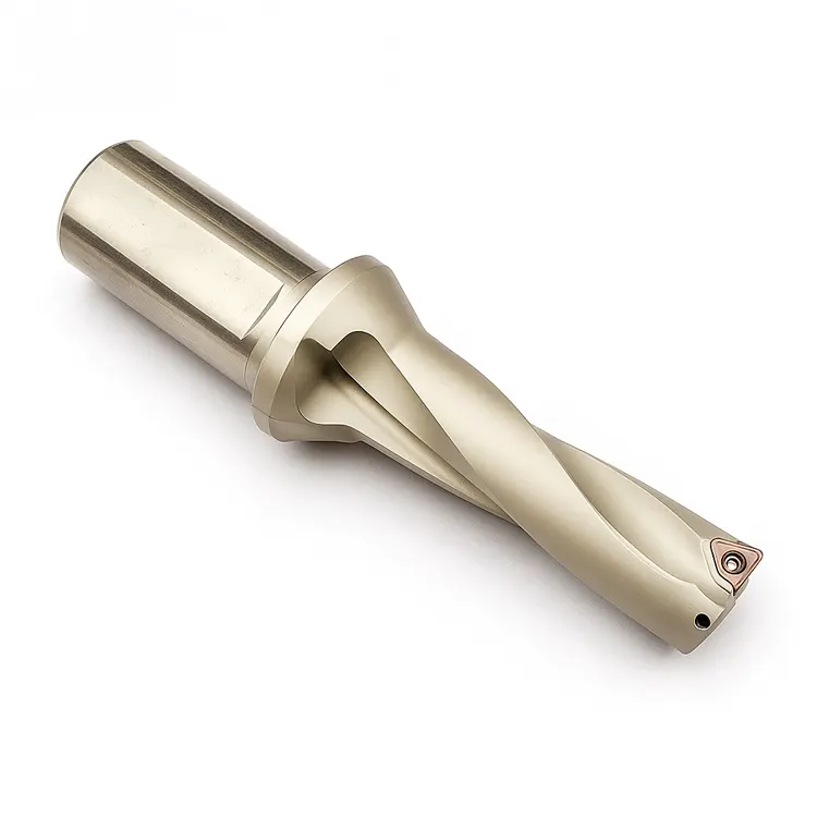
Indexable drills are high-performance hole-making tools that use replaceable carbide inserts instead of a solid cutting edge. In machining centers, they offer higher material removal rates (MRR), eliminate the need for spot drilling, and allow for versatile operations like boring and chamfering with a single tool.
The Evolution from HSS to Indexable
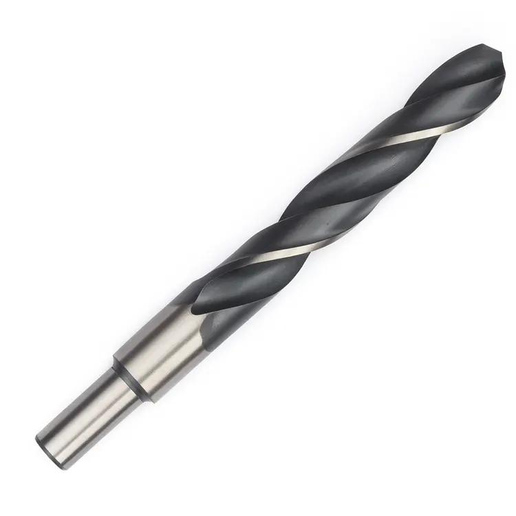
I remember the first time I swapped a 1-inch HSS twist drill for a 1-inch indexable drill on a VF-4. The difference wasn’t just in speed; it was in the workflow. With HSS, we had to spot drill, peck drill to clear chips, and regrind the tool constantly.
With indexable drills, we eliminated the spot drill entirely. We stopped pecking. We pushed the feed rate from 4 inches per minute (IPM) to 12 IPM. The cycle time dropped by 70%. That is the power of modern insert technology.
Key Benefits:
- Cost Efficiency: When an edge wears out, you rotate the insert. You don’t scrap the whole tool.
- Rigidity: The body is thicker and shorter than twist drills, reducing wandering.
- Versatility: You can offset the tool to adjust hole size (more on this later).
How does drilling in a mill differ from a lathe?
In a lathe, the workpiece rotates while the drill remains stationary; in a machining center, the drill rotates while the workpiece is stationary. This fundamental difference changes how chips evacuate and how alignment issues affect the final hole tolerance, requiring specific attention to tool runout and coolant pressure.
The Physics of Rotation
This distinction is vital. On a lathe, if your drill is slightly off-center, you end up with a “pip” in the center of the hole. For a deeper dive into turning applications, read our guide on how to use indexable drills on a lathe.
However, in a machining center, runout (wobble) is your enemy. If the tool holder isn’t running true:
- The drill creates an oversized hole.
- The peripheral insert takes an excessive load.
- Tool life decreases drastically.
Expert Tip: Always measure the Total Indicator Runout (TIR) of your indexable drill in the holder. If it exceeds 0.002″ (0.05mm), you need to clean the taper or change the collet/holder.
How do you set up an indexable drill correctly?
Proper setup requires a high-rigidity holder (preferably side-lock or hydraulic), verifying zero runout, and ensuring high-pressure through-spindle coolant. Never use a drill chuck for indexable drilling, as the radial forces will loosen the chuck jaws and cause catastrophic failure.
Step-by-Step Setup Protocol
To ensure process reliability, follow this rigid setup process. For a broader look at machine preparation, refer to our CNC setup optimization guide.
- Select the Holder:
- Side-Lock (Weldon): The industry standard. It offers immense pull-out protection. Ensure the flat on the drill aligns perfectly with the screw.
- Hydraulic Chucks: Excellent for reducing runout and dampening vibration, but ensure they are rated for the torque.
- ER Collets: Generally avoid these for large diameter indexable drilling unless using a sealed collet for coolant. They lack the grip of a side-lock.
- Insert Orientation:Most indexable drills have two inserts:
- Central Insert: Cuts the center (zero speed point).
- Peripheral Insert: Cuts the outer diameter (high speed point).
- Critical Check: Ensure the screws are torqued to manufacturer specs. A loose screw at 3,000 RPM is a bullet.
- Coolant Connection:Through-Spindle Coolant (TSC) is mandatory. Without it, chips pack in the flutes instantly. If your machine lacks TSC, you must use a coolant inducer holder, though this is less rigid.
What are the correct feeds and speeds for indexable drills?
Indexable drills require high RPM and aggressive feed rates to break chips effectively; running them too slow causes “rubbing” and work hardening. A general starting rule for steel is 400-600 SFM (Surface Feet per Minute) and 0.003-0.006 inches per revolution (IPR), depending on the insert grade.
The “Don’t Baby It” Rule
A common mistake I see with junior machinists is fear. They run the drill slow because it looks aggressive. This kills the tool.
Indexable inserts need pressure to shear the metal. If you feed too lightly (under 0.002 IPR), the insert rubs against the material rather than cutting it. This generates immense heat and glazes the material.
Calculating the Sweet Spot:
- RPM: $RPM = (SFM \times 3.82) / Diameter$
- Feed: Start at the manufacturer’s recommended mid-range.
For detailed formulas on dialing in your spindle speed, check our RPM setup guide. Similarly, if you are struggling with chip breaking, review our specific feed rate setup for indexable drills.
Material Specific Parameters Table:
| Material | SFM (Range) | Feed (IPR) | Coolant Pressure |
| Low Carbon Steel | 600 – 900 | 0.004 – 0.008 | High |
| Alloy Steel (4140) | 400 – 600 | 0.003 – 0.006 | High |
| Stainless (304/316) | 350 – 500 | 0.003 – 0.005 | Very High |
| Aluminum (6061) | 1200 – 2000 | 0.008 – 0.012 | High |
| Cast Iron | 500 – 700 | 0.006 – 0.010 | Air/Coolant |
Note: Always consult the insert box for the exact grade capabilities. These are starting points.
Why is Through-Spindle Coolant (TSC) critical?
Through-Spindle Coolant is critical because it blasts chips out of the hole from the bottom up, preventing chip recutting and flute packing. In deep hole applications (3xD or greater), external coolant nozzles cannot reach the cutting zone, leading to rapid heat buildup and catastrophic tool welding.
The Mechanics of Evacuation
When an indexable drill is 3 inches deep in a block of 4140 steel, the cutting zone is a chaotic environment.
- Heat: Temperatures can exceed 1000°F.
- Expansion: Chips occupy more volume than the solid metal they came from.
If you rely on flood coolant (external nozzles), the liquid hits the top of the hole and spins off. The cutting edge runs dry. With TSC, the fluid travels through the tool body and exits directly at the cutting edge. This does two things:
- Lubricity: Reduces friction at the shear zone.
- Kinetic Energy: The pressure (ideally 300+ PSI) physically forces chips up the flutes and out of the hole.
How can you adjust hole diameter using offsets?
You can adjust hole diameter on a machining center by offsetting the tool axis slightly, effectively turning the drill into a boring bar. By moving the drill off-center toward the peripheral insert, you can increase the hole size, but you can never decrease the size below the drill’s nominal diameter.
The “Bonus” Feature of Machining Centers
This is a technique that separates operators from machinists. Let’s say you have a 25mm drill, but you need a 25.2mm hole. You don’t need a boring head.
How to do it:
- Identify the Peripheral Insert: Determine which side of the tool holds the outer insert.
- Orient the Spindle: Use a command (like
M19on Fanuc) to lock the spindle orientation. - Shift the Axis: Program a move that shifts the tool slightly in the direction of the peripheral insert.
- Helical Interpolation (Alternative): You can also use helical interpolation with an indexable drill to open up a hole significantly, though this is harder on the inserts.
Caution: Do not offset more than the manufacturer allows (usually 0.5mm to 1.0mm max). Exceeding this causes the drill body to rub against the un-cut material on the opposite side. For more on maintaining tight tolerances, read about hole accuracy in CNC drilling.
What is the correct entry strategy?
The correct entry strategy involves entering the cut at a reduced feed rate (50-70%) until the full diameter is engaged to stabilize the tool. Once the drill is fully engaged in the material, ramp up to 100% feed rate to ensure proper chip breaking and stabilize the cutting forces.
Dealing with Uneven Surfaces
Indexable drills hate uneven surfaces. If you are drilling into a slanted surface or a casting with a rough skin:
- Spot Facing: Use a milling cutter to create a flat spot first.
- Pilot Hole: If you can’t mill a flat, use a pilot drill (same diameter or slightly larger) to start the hole.
- Reduced Entry: If you must enter on a slant, reduce feed by 50% or more until the drill is fully supported by the hole walls.
Troubleshooting: Why is my drill screaming or failing?
Drills usually scream or fail due to low feed rates causing rubbing, excessive runout causing vibration, or lack of coolant pressure packing chips. Identifying the specific sound and wear pattern on the inserts is the fastest way to diagnose the root cause.
Diagnostic Table
| Symptom | Probable Cause | Corrective Action |
| High-Pitched Squeal | Feed rate too low (Rubbing) | Increase feed rate by 10-20%. |
| Low-Pitched Rumble | Unstable setup / Vibration | Check runout; use a shorter holder. |
| Chipped Outer Corner | Speed (RPM) too high or Runout | Reduce SFM; Check TIR. |
| Chipped Inner Insert | Feed rate too high | Reduce feed rate; check center height. |
| Drill Body Wear | Chip packing | Increase coolant pressure; check flute condition. |
| Bird-nesting Chips | Feed too low (not breaking chips) | Increase feed rate to snap the chip. |
The “Disc” Indicator
When you drill a blind hole with an indexable drill, there is often a small disc or “slug” left at the bottom center. This is normal.
- If the disc is gone: Your center insert might be chipped or your alignment is off.
- If the disc is huge: Your inserts may be spaced incorrectly (check for wrong insert size).
Frequently Asked Questions (FAQ)
Can I stack indexable drills?
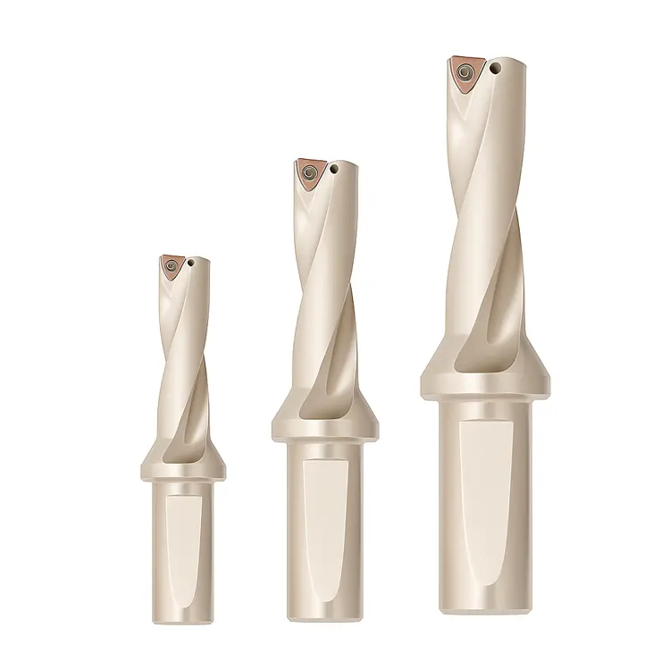
It is not recommended to stack multiple extensions. Every interface reduces rigidity and multiplies runout. If you need reach, buy a longer L/D (Length-to-Diameter) ratio drill body (e.g., 5xD or 8xD).
Can I use indexable drills on aluminum?
Absolutely, but you must use polished inserts specifically designed for non-ferrous materials. Standard CVD coated inserts for steel will cause aluminum to stick (built-up edge), clogging the flutes instantly.
Why did my drill melt?
This is almost always a coolant failure. If the coolant stops for even 2 seconds while the drill is buried in steel, the heat generates instantly. Ensure your pump filters are clean and you have flow confirmation sensors active.
Conclusion: Drills that Pay the Bills
Implementing Indexable Drills in Machining Centers is one of the highest ROI changes you can make in a machine shop. They are faster, stiffer, and more adaptable than traditional tooling.
By following the rules of rigidity, ensuring proper coolant flow, and having the courage to push the feed rates to the proper levels, you will see a dramatic improvement in your floor-to-floor times.
Ready to optimize your entire machining workflow?
Start by ensuring your setup is rigid enough to handle these forces. Review our CNC setup optimization guide to build the foundation for high-speed drilling success.