







Common Mistakes When Using a Countersink Drill Bit on Wood
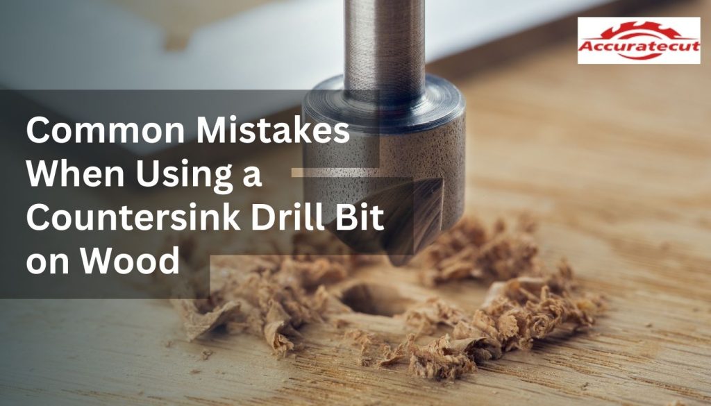
A countersink drill bit is not merely a cosmetic tool used to hide fastener heads. In wood engineering, countersinking alters local stress distribution, fiber compression patterns, and load transfer behavior between fasteners and substrate. Small deviations in countersink geometry, depth, or feed rate can change joint performance by measurable margins, including reduced pull-through resistance, increased micro-cracking around screw heads, and long-term loosening due to cyclic loading. When combined into a countersink and drill bit system, tool geometry and alignment directly influence screw seating mechanics, surface integrity, and joint lifespan.
Misalignment Between Screw Head Angle and Countersink Geometry:
Why Incorrect Included Angle Creates Stress Concentration
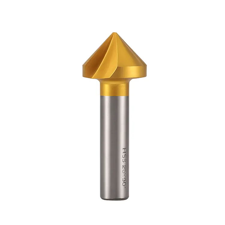
Most wood screws use an 82° head angle, whereas many generic countersink drill sizes are manufactured at 90°. This 8° mismatch appears minor but produces a non-uniform contact ring when the screw seats. Instead of the screw head distributing compressive load evenly across the countersink face, contact occurs primarily along the outer rim of the recess.
From a mechanics perspective, contact stress increases as contact area decreases. If a correctly matched 82° countersink provides approximately 85–95% surface contact, a 90° cutter may reduce effective bearing area to 40–60%, depending on depth error. This doubles local compressive stress in wood fibers, accelerating fiber crushing in softwoods and micro-fracturing in hardwoods. Over time, this localized damage increases embedment deformation, allowing the screw head to sink further under load, which leads to joint loosening in cabinets and furniture frames.
Tool Geometry and Fiber Shear Direction
Wood-specific countersink cutters use lower rake angles and polished relief surfaces to promote shearing rather than scraping. Metal-oriented countersinks use aggressive rake profiles that increase radial cutting forces. In wood, this radial force exceeds the tensile strength of surface fibers, causing circumferential tear-out around the countersink lip. The failure mechanism is fiber tension rupture rather than clean shear, resulting in rough edges that compromise finish quality and increase moisture ingress pathways.
Pilot Hole and Countersink Interaction Errors
Why Countersinking Before Drilling the Pilot Hole Causes Off-Axis Load
Countersinking before drilling removes surface material without a centering reference. This causes radial cutter drift of 0.2–0.6 mm in softwood and up to 0.3 mm in hardwood due to density variation across growth rings. When the pilot hole is drilled afterward, the screw axis becomes offset relative to the countersink center.
This eccentricity introduces bending stress in the screw shank during tightening. Instead of axial load transfer, the screw experiences combined axial compression and lateral bending. This reduces holding capacity by up to 15–25% in cabinet-grade plywood and increases the risk of screw head cam-out during installation.
Quantifying Pilot Hole Diameter Errors
Pilot hole diameter should typically be 70–85% of the screw’s root diameter in softwood and 85–95% in hardwood. When countersink drill sizes are selected without matching pilot geometry, two failure modes occur.
If undersized by more than 10%, radial hoop stress exceeds the tensile strength of wood fibers near the countersink lip, producing micro-cracks that propagate outward.
If oversized by more than 10%, thread engagement length decreases, reducing pull-out strength by 20–40% depending on wood density.
Depth Control Errors and Structural Consequences
Why Over-Countersinking Weakens Load Transfer
Over-countersinking removes the load-bearing annulus of wood that supports the screw head. The load from the screw head is transferred into the wood over a thin ring of fibers at the countersink perimeter. When countersink depth exceeds screw head height by more than 0.5 mm, this annular region becomes too thin to distribute compressive stress effectively.
Compression testing shows that softwood fibers begin permanent deformation at approximately 2–4 MPa, while hardwood fibers tolerate 5–8 MPa. Over-countersinking concentrates stress beyond these limits, causing progressive embedment under load. This embedment increases screw head settlement, loosens joints, and reduces clamping force in cabinet carcasses over time.
Why Inconsistent Depth Complicates Plug Seating
Consistent depth allows plugs to seat flush without excessive sanding because wood plugs rely on interference fit and uniform contact pressure. When countersink depth varies by more than ±0.3 mm, plug insertion depth varies accordingly. Shallow recesses cause proud plugs that require aggressive sanding, thinning the surrounding veneer. Deep recesses create low contact pressure zones where glue lines are too thick, reducing adhesive shear strength by up to 30%. This leads to visible plug outlines after finishing due to differential shrinkage.
Speed and Feed Rate Mismanagement
Why Excessive RPM Causes Thermal Degradation
At spindle speeds above 3,000 RPM for 12 mm countersinks in hardwood, frictional heating raises cutter edge temperature beyond 120°C. At this temperature, resin in softwoods begins to soften and smear across flutes, reducing cutting efficiency. Wood fibers near the surface undergo thermal degradation, darkening due to partial pyrolysis. This thermal damage reduces surface hardness and compromises finish adhesion.
Why Low Feed Rates Increase Tear-Out
When feed rate is too low, chip thickness falls below the minimum shear thickness of wood fibers, causing the cutter to rub rather than cut. This rubbing action plastically deforms fibers instead of severing them, producing fuzzy edges. In veneer layers as thin as 0.6 mm, this deformation exceeds veneer tensile capacity, causing delamination around the countersink lip.
Grain Orientation and End-Grain Countersinking Mechanics
Why Countersinking Across End Grain Causes Splintering
End grain presents exposed fiber ends with low transverse tensile strength. When a countersink drill bit engages end grain, radial cutting forces act perpendicular to fiber direction. The tensile strength of wood perpendicular to grain is 5–20 times lower than parallel to grain. This means radial forces easily exceed fiber cohesion, causing splintering and uneven recess formation.
Additionally, end grain lacks lateral fiber support, so cutter forces propagate cracks deeper into the board. This creates subsurface fractures that may not be visible initially but later appear as finish cracks around screw heads.
Depth Per Pass and Stress Mitigation
Reducing countersink depth per pass lowers peak radial stress on fibers. By limiting depth increments to 0.3–0.5 mm per pass in hardwood end grain, radial force is reduced below fiber tensile failure thresholds, minimizing splintering.
Runout, Concentricity, and Chuck Errors
Why Runout Enlarges Countersink Diameter
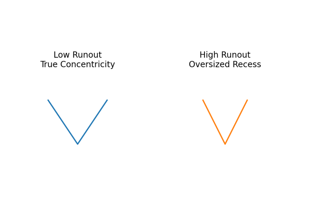
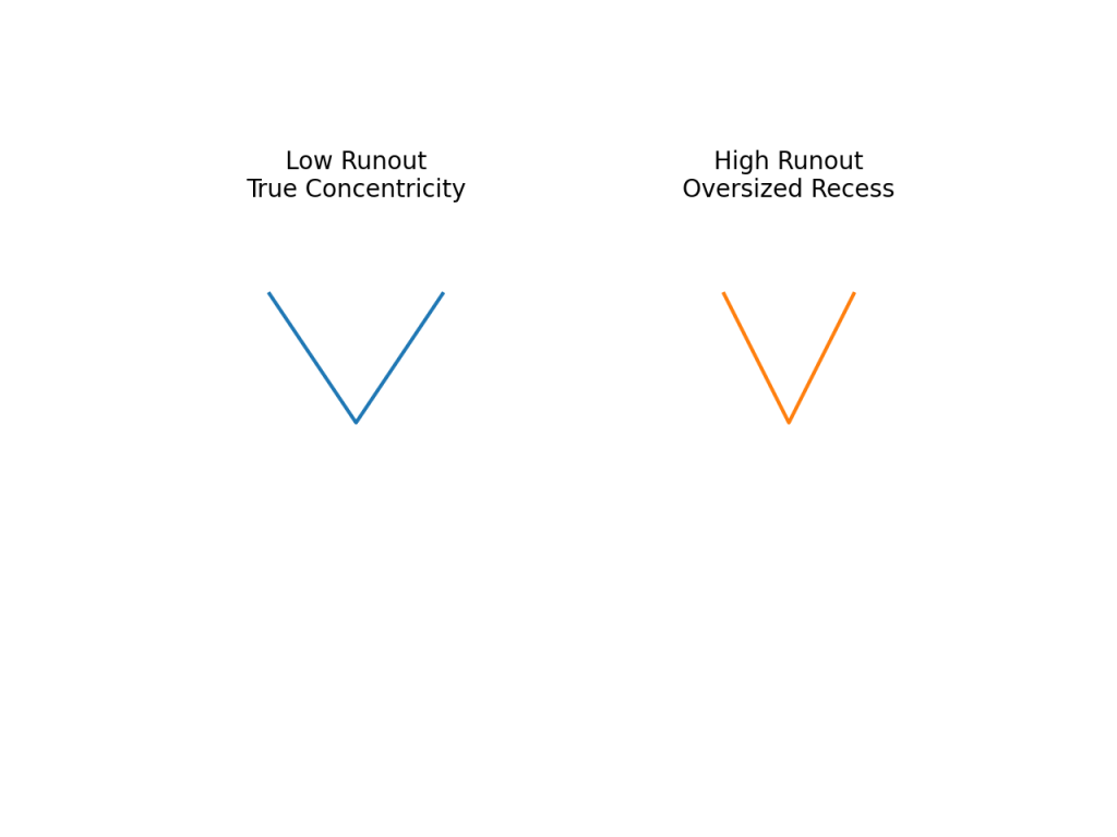
Chuck runout greater than 0.15 mm causes eccentric rotation of the countersink cutter. This increases effective cutting diameter by 0.3 mm or more, producing oversized recesses. Oversized countersinks reduce bearing area under the screw head, increasing compressive stress and reducing resistance to pull-through. In cabinetry applications, this reduces long-term holding power of hinge and rail fasteners.
Concentricity in Countersink and Drill Bit Assemblies
In a countersink and drill bit system, misalignment between pilot drill and countersink cutter causes non-concentric recesses. This forces the screw to seat at a slight angle, creating uneven contact pressure and localized fiber crushing. Over repeated load cycles, this asymmetry leads to progressive loosening.
Veneered Panels and Cabinetry-Specific Failures
Why Veneer Chips Under Standard Countersinks
Veneer layers fail because standard flutes lift fibers upward before severing them. The upward force exceeds adhesive bond strength between veneer and substrate, causing edge lifting. Zero-flute or shear-flute designs reduce upward force vectors, maintaining veneer adhesion.
Why Cabinet Installations Lose Holding Power
Cabinet frames experience cyclic loading from door movement. Improper countersink drill bit for cabinets usage reduces initial clamping force by damaging fiber support under screw heads. Over thousands of open-close cycles, micro-compression under the screw head causes progressive loosening. This is why cabinets with poorly executed countersinks develop hinge sag over time.
Calibration, Test Cuts, and Risk Management
Why Test Cuts Prevent Irreversible Surface Damage
This allows calibration of feed rate, RPM, and depth settings without risking visible surfaces because wood is anisotropic and variable in density. A 10–15% density difference between boards can change optimal RPM by several hundred revolutions per minute. Without test cuts, incorrect parameters cause tear-out, burn marks, or over-countersinking on finished panels, which cannot be fully repaired without visible defects.
Risk of No Calibration in Production Work
Skipping test cuts leads to cumulative error across multiple fasteners. In cabinet production, small depth errors repeated across dozens of screws create uneven surface planes that require aggressive sanding, thinning protective coatings and reducing surface durability.
Tool Quality and Countersink Drill Bit Set Limitations
Metallurgy and Edge Retention
Low-grade countersink drill bit sets use unhardened carbon steel that loses edge sharpness rapidly. Edge rounding increases cutting force requirements by 20–35%, raising tear-out risk and operator-induced misalignment. Professional sets use hardened HSS or carbide tips that maintain geometry under thermal load.
Inconsistent Countersink Drill Sizes
Manufacturing tolerances in low-quality sets vary by ±0.2–0.4 mm. This inconsistency produces uneven recess diameters across a project, complicating plug fitting and reducing uniform load distribution under screw heads.
Long-Term Structural Consequences of Poor Countersinking
Fatigue and Progressive Loosening
Improper countersinking introduces stress risers at the recess edge. Under cyclic loads, micro-cracks form and propagate, reducing local stiffness. Over time, this leads to screw head settlement and loss of preload, weakening joints in furniture and cabinets.
Moisture Ingress and Finish Failure
Rough countersink edges increase surface area and micro-voids where moisture accumulates. This accelerates localized swelling, causing finish cracking and plug outlines to telegraph through coatings.
Conclusion
Precision countersinking in wood is a mechanical operation governed by geometry, stress distribution, thermal behavior, and material anisotropy. Errors in countersink drill bit selection, countersink and drill bit alignment, countersink drill sizes, and depth control directly affect joint strength, surface integrity, and long-term durability. High-quality countersink drill bit set tools, correct calibration, and material-specific cutting parameters are not optional refinements but structural necessities, especially when performing high-load or visible cabinetry work with a countersink drill bit for cabinets.
Frequenty Asked Questions:
How to use a countersink drill bit for wood?
Drill the pilot hole first, then apply the countersink using the pilot as a guide. Keep the tool perpendicular, use moderate RPM (lower for hardwood), and stop when the screw head sits flush without crushing surface fibers.
Which drill bit is good for wood?
Brad-point drill bits are best for wood because the center spur prevents wandering and the outer spurs shear fibers cleanly. Twist drill bits for metal tend to burnish and tear wood fibers.
What is a countersink drill bit for?
It creates a conical recess so flat-head screws sit flush or slightly below the wood surface, improving load distribution and surface finishing.
What's the difference between countersink & counterbore?
A countersink creates a conical recess for flat-head screws, while a counterbore creates a flat-bottomed cylindrical recess for bolt or socket-head screws.
What are the two main reasons to use a countersink?
To seat screw heads flush for clean finishing and to distribute compressive load under the screw head to reduce fiber crushing and loosening.
What are two reasons why a hole may need to be countersunk?
To prevent screw heads from protruding above the surface and to reduce surface cracking or chipping around the fastener.
What are the five types of drill bits?
Brad-point (wood), twist (general-purpose/metal), spade (fast rough wood drilling), auger (deep wood drilling), and Forstner (flat-bottom holes in wood).
How do you choose the right countersink bit?
Match the countersink angle to the screw head (commonly 82° for wood screws), select the correct countersink drill sizes for the fastener, and use wood-specific cutters for clean fiber shearing.
What is another name for a countersink bit?
A countersink bit is also called a chamfer bit or screw countersink.
